Name plate, Installation, Control unit lrr 1- 40 – Flowserve LRR1-40 TDS Control Unit User Manual
Page 13: Tools, Control unit lrr 1- 40 tools, Fig. 3, Temperature range
13
– co ntinued –
Name plate
Installation
Control unit LRR 1- 40
The control unit LRR 1- 40 is installed in a control cabinet on a supporting rail
type
TH 35, EN 60715.
1.
Clip casing
with the upper mounting rail onto the support rail
. When the
casing
snaps into place a clicking sound can be heard.
2.
Make sure that the white mounting slide is correctly located.
3.
Align the control unit horizontally on the support rail
.
Tools
■
Screwdriver, size 5.5 /100
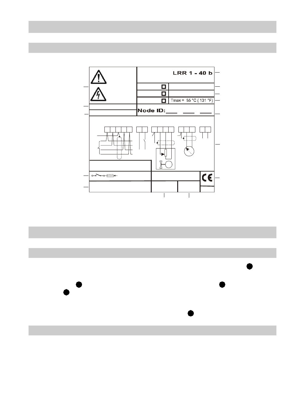
Safety note
Equipment
designation
Pressure/
Wiring diagram
Power rating
Input characteristics
CE marking
Node- ID
Manufacturer
Spare part specification
Protection
Fuse
Mains supply
Fig. 3
temperature range
GESTRA AG
Münchener Str.77, D-28215 Bremen
250 V ~ T 2,5 A
Steuergerät
Control device
Appareil de commande
24 V
115 V
230 V
IP 40 (IP20)
50 / 60 Hz 5 VA
Betriebsanleitung
beachten
See installation
instruc tions
Voir instructions de
montage
US Pat.5 805 052
1 2 3 4 5
7 8
S
24V
DC
24V AC/DC
stand-by
CAN-BUS
-
C
H
C
L
+
+
IN / OUT: CAN-Bus
18-36 V DC
S
17
16
L N
11
10
9
12
15
14
-
+
X ext
4-20 mA
13
S
S
+
-
M
Mat.Nr.:
0525
VS.-Nr.:
TÜV.WÜL. 02 - 007
F
E
F
E
F