Flowserve BTV 2000 Lined Butterfly Valve User Manual
Page 17
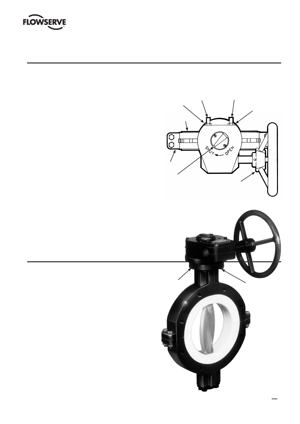
1. Close the valve. The flats on top of the stem should be
parallel with the valve flange face. NOTE: At this time
adjustments should be made to assure that the valve
body machined flanged surface (6) is parallel with the
disc. To accomplish this, place the valve body machined
flanged surface (6) on a level plate. Then position a
bubble level on the upper side of the shaft square and
adjust the shaft until com pletely level.
2. Rotate the gearbox handwheel (1) clockwise until the
gearbox pointer (2) indicates the “shut” position.
3. Place the gearbox on the valve mounting pad as shown in
Figure 26.
4. Loosen the gearbox stopping screws (3) and (7).
5. Install and tighten the gearbox bolts (4) with their
lockwashers.
6. Turn the gearbox closing stop screw (7) clockwise until it
stops, then tighten the lock nut (8).
7. Turn the gearbox handwheel (1) counterclockwise to
open the valve until the disc face is perpendicular to the
valve body flange face.
8. Turn the gearbox opening stop screw (3) clockwise until
it stops, then tighten the lock nut (5).
9. Cycle the valve from closed to open to closed again
using the gear operator. Recheck to make sure the disc
is centered on the seat by measuring the distance from
the machined surface on the disc edge to the inner edge
of the liner flanged surface (6) on the body. This should
be done at two points, at the 3 o’clock and 9 o’clock
positions. Both measurements should be equal.
Figure 26
SECTION VII
MANUAL GEAR OPERATOR INSTALLATION
SECTION VIII
CHANGING MANUAL GEAR OPERATOR QUADRANTS
CAUTION:
Do not attempt to change the manual gear
operator quadrant while the valve is in service.
1. Close the valve. The flats on top of the stem should be
parallel with the valve flange face. Depressurize system if
valve is installed as valve could open when manual gear
operator is removed.
2. Remove manual gear operator. Rotate the gearbox
handwheel (1) until the gearbox pointer (2) indicates the
“shut” position.
3. Place the gearbox on the valve mounting pad in the
desired quadrant.
4. Follow Steps 4 through 8 of the Manual Gear Operator
Installation instructions.
Gearbox Stop
Screw (7)
Lock Nut (8)
Machined Flanged
Surfaced (6)
Body
Gearbox
Pointer (2)
Gearbox Stop
Screw (3)
Lock Nut (5)
Gearbox
Handwheel (1)
Mounting
Pad
Gearbox
Bolts (4)
17
BTV/BUV 2000
- BUV 2000 Lined Butterfly Valve McCANNA General Purpose Threaded MARPAC General Purpose Threaded Cartridge Seals 582 Mixerpac 2561 Mixerpac 2562 Mixerpac 579 Mixerpac 2563 Mixerpac 2564 Mixerpac 591 Mixerpac 581 Mixerpac 587 Mixerpac ML-200 Mixerpac 2577 Mixerpac 2554 Mixerpac 588 Mixerpac 585 Mixerpac Seal Gard Circpac MD Nordstrom Dynamic Balance Plug Valve and Double DB Plug Valve Serck Audco Super-H Plug Valve Serck Audco Twin Isolation Plug Valve Serck Audco Double Isolation Plug Valve Serck Audco Standard Type Plug Valves 51 Series 52 Series