Reassembly instructions, Cont.) – Flowserve V-378 R1 Edward Equiwedge Gate Valve User Manual
Page 21
21
Flow Control Division
Edward Valves
Reassembly instructions
(cont.)
Tapered Roller Bearing
Preload Instructions
1. Bearing Assembly - Install the bear-
ings, grease seals and yoke bushing
in the yoke.
2. BEARING PRELOAD WARNING –
FAILURE TO FOLLOW INSTRUC-
TIONS MAY RESULT IN BEARING
FAILURE. See illustration No. 16.
a. Use a micrometer to measure the
thickness of the bearing retainer
flange at each measurement hole.
Number each measurement hole
with a grease pencil. Record the
measurements.
b. Mark the bearing retainer flange
and yoke with a grease pencil in
order to know the relative position
of parts and remove the bearing
retainer flange.
c. Use a micrometer to measure the
thickness of the “bearing preload
washer” and record the measure-
ment.
d. Install a “bearing preload washer”
(tool). See Table 4 for dimensions.
Install the bearing retainer flange
(make certain that mating surfaces
are clean) at alignment position
marks and align the bolt holes.
Install 3 or 4 cap screws to secure
the bearing retainer at 90° or
120° intervals. Use a depth
micrometer to level the bearing
retainer flange and take readings
to ensure that the flange remains
level as the torque is increased in
small increments. The preload
torque is indicated in Table 5 for
each applicable cap screw size.
Rotate the yoke bushing after each
increase in torque.
e. Extend a depth micrometer into
each of the holes located in “a”
above until it hits the top of the
yoke. Record the measurements.
Calculate the average dimension
and record.
f. Remove the bearing retainer
flange, cap screws and bearing
preload washer (tool).
g. Add the average dimension
recorded in “a” to the measure-
ment recorded in “c” and record
the result.
h. Subtract the measurement record-
ed in “e”from the average dimen-
sion recorded in “g” and record
the result.
i. Shim stock thickness equal to the
result recorded in “h” must be
installed between the top bearing
and the bearing retainer flange.
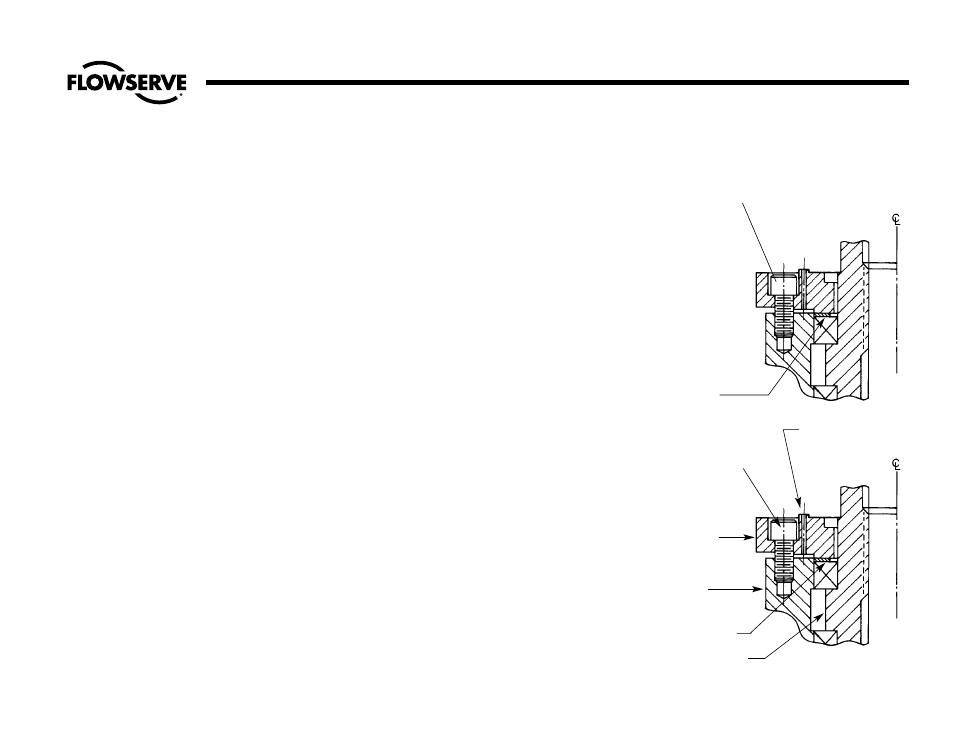
Illustration No. 16
Bearing Preload Instruction
PRELOAD CAP SCREWS
TORQUE FROM TABLE 5
PRELOAD WASHER
TABLE 4
CAP SCREWS TORQUE
FROM TABLE 5
BEAR RETAINER
FLANGE
YOKE
SHIM STOCK
YOKE BUSHING
3 MEASURING HOLES