Table ii: post/shaft plug torques (ft.-lbs.) – Flowserve Valtek ShearStream HP Control Valves User Manual
Page 9
®
User instructions - Shearstream HP - VLENIM0027-01 03.08
9
On stationary post designs, Ensure that the post
and post threads are well lubricated with a high
temperature bearing grease (or as required by the
application) before installation. Replace the post
O-ring and reinstall the post. Torque the post per Table II.
Install the anti-rotation clamp kit.
8..9 Slide thrust bearing, packing spacer, packing, and packing
follower over the splined end of the shaft and into body.
Typical packing configurations are shown in Figure 3. (-inch
designs refer to Step 6.)
NOTE: Always use new packing whenever rebuilding the
packing box.
CAUTION: Since the sealing on V-ring packing takes place
at the feather edge, it is imperative to avoid damage to
that edge.
8..0 Reinstall the gland flange and packing nuts and leave
loose.
CAUTION: Do not overtighten packing. This can cause
excessive packing wear and shaft friction, which may
impede shaft rotation.
8.. Place the valve on a flat surface with the threaded (retainer)
port facing up and pull the shaft toward the actuator until it
is fully against the thrust bearing.
8.. On 3 – 12-inch and 16-inch designs, make certain the
ball surface is facing up and position the ball as close as
possible in the center of the body‘s inside diameter. (The
pinned connection between the ball and shaft is not a tight
connection; the design includes a considerable amount of
axial play between the ball and shaft.)
On 1 – 2-inch designs, make certain the ball surface is fac-
ing up and pull on the shaft until the post is fully against the
thrust bearing. (The ball does not self center. No axial play
should occur between the ball and shaft.)
8..3 Replace the seat as applicable to the valve. (Refer to Figure 4.)
For metal seats, insert the two metal seal rings into the body.
(See note on Figure 4.)
For soft seats, insert the soft seal ring into the body.
For dual seats, insert the soft seal ring, followed by the
two metal seal rings into the body. (See note on Figure 4.)
For heavy duty metal seats or heavy duty soft seats, first
lubricate the seat o-ring and install into the seat. Next lu-
bricate the mating surfaces between the seat and seat re-
tainer. Then place one shim in the retainer, followed by all
of the wave springs, and then the remaining shims. Next
place the seat into seat retainer, so the seat is resting on
the shims and wave springs. For heavy duty metal seats,
lubricate the contact surfaces between the seat and ball.
Follow instructions in 8..4 for simultaneously installing
the seat retainer and heavy duty seat into the body.
8..4 With screwed-in retainer designs, replace the
O-rings in the retainer (except on high temperature valves,
which do not use O-rings). Refer to Figure or . Lubricate
the retainer threads and rings and reinstall the retainer in
the front of the body. Torque the seal retainer according to
Table III.
8..5 On some 0, and 6-inch valves where the retainer is held
in place with set screws, reinsert the lock ring into the body
with the words ‘Ball Side’ facing toward the ball. The lock
ring has ‘Ball Side’ and ‘Port Side’ marked on it. Insert the
retaining ring into the inner groove of the body, being certain
it is fully seated. Tighten the lock ring setscrews evenly to a
torque of 5 inch-pounds.
8..6 After the seal retainer is in tight, tighten the packing nuts
just over finger-tight. Packing nuts should be tightened as
necessary to prevent stem leakage.
CAUTION: Do not overtighten packing. This can cause
excessive packing wear and high shaft friction, which may
retard shaft rotation.
9
Remounting the Actuator
Before mounting a Flowserve actuator on the valve body,
verify that the ball rotation matches the actuator rotation
and complies with the air failure requirements. Procedure
for mounting the actuator is as follows:
9.
Slide the entire actuator assembly onto the shaft. (If neces-
sary on Flowserve actuator designs with clamped lever-arm
design, wedge the splined lever arm apart to loosen it on the
shaft splines.)
9.
Bolt the yoke to the valve body.
9.3
Position the actuator lever arm on the shaft so the actuator
stem is centered in the transfer case.
9.4
On clamped lever-arm actuator designs, firmly tighten the
linkage bolt. Bolt the transfer case cover plate into place.
9.5
Align the stroke indicator plate on the end of spline lever so
it accurately indicates ball position.
CAUTION: On clamped lever-arm actuators, never apply air
to the actuator without the cover plate installed; otherwise,
the unsupported shaft may sustain damage.
9.6
Install valve in line as outlined in Installation section.
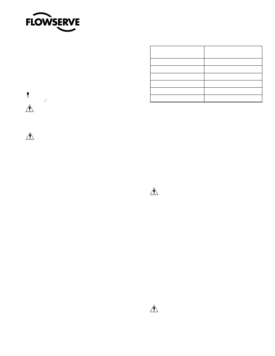
Table II: Post/Shaft Plug Torques (ft.-lbs.)
Valve Size
(inches)
Rotating Post Design
(Shaft Plug)
, .5*
50
*
85
3, 4
50
6,8
50
0,
300
6*
N/A
* Flanged post; torque values not required.