Figure 2: 1 – 2-inch shearstream hp body assembly – Flowserve Valtek ShearStream HP Control Valves User Manual
Page 6
®
User instructions - Shearstream HP - VLENIM0027-01 03.08
6
the actuator prior to body disassembly is necessary. Refer
to Figures , and 5 and proceed as follows:
8.. Remove the seal retainer and seals.
Screw-in style – This requires loosening the retainer by
turning it counterclockwise and removing it from the body.
(A special cross-wrench tool may be ordered from the fac-
tory. See Table IV.) Remove the metal seals. Remove the
soft seal if applicable.
Lock-ring style – Some valve designs have a retaining ring
held in with set screws. To remove it, loosen the set screws
in the lock ring, then remove the retaining ring, lock ring
and finally the seal retainer. If the lock ring set screws will
not loosen, the retaining ring can be forced out using a
flat-headed screwdriver and pliers. Remove the seals.
8.. Remove the gland flange by removing both packing nuts.
Removing the studs is not necessary.
8..3 On rotating post designs, drive both the shaft and post pins
into the center of the shaft and post until the outward end of
the pin clears the ball. Be careful to not damage the shaft or
post. The pins can then be punched out of the shaft and post
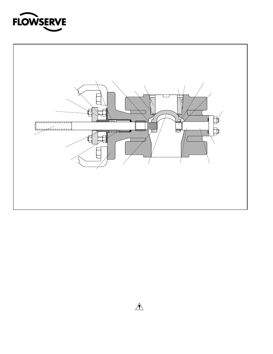
Figure 2: 1 – 2-inch ShearStream HP Body Assembly
(*See Figure 4 for seal configurations and item numbers.)
NOTE: Item numbers correspond directly to the valve‘s bill of material. Refer to it for specific part numbers.
Packing
(Item No. 88)
Packing Stud
(Item No. 09)
Gland Flange
(Item No. 80)
Packing Nut
(Item No. 7)
Shaft
(Item No. 5)
Packing Follower
(Item No. 87)
Packing Spacer
(Item No. 93)
Post
(Item No. 3)
Post O-ring
(Item No. 64)
(optional)
Shaft Bearing
(Item No. 83)
Retainer O-rings
(Item No. 59)
(Item No. 56)
Retainer
(Item No. 30)
Plug
(Item
No. )
O-ring
(Item No. 6)
Pin
Ball
Post Bearing
(Item No. 5)
(Item No. 50)
(Item No. 84)
Thrust Bearing
(Item No. 53)
Body
(Item No. )
Seals*
Inboard End
when they are removed from the valve. Carefully remove the
shaft plug and O-ring and finally the rotating post. (Inserting
a bolt in the jack screw hole, tapped in the post, will help in
removing the post.)
On stationary post designs, drive the shaft pin into the
center of the shaft until the outward end of the pin clears the
ball splines. Be careful to not damage the shaft. The pin can
then be punched out of the shaft after the shaft is removed.
Remove the anti-rotation clamp. Remove the post and the
post O-rings.
8..4 On 3 – -inch and 6-inch designs, remove the shaft by
pulling it out through the outboard end of the body. On
– -inch designs, remove the shaft by pulling it out through
the inboard end of the body
CAUTION: Take special care to not damage the splined end
of valve shaft during disassembly.
8..5 Rotate the ball inside the body so the non-splined end of
the ball is toward the back port of the valve and remove the
ball straight out of the body. If necessary, on stationary post
designs remove the post bearing from the ball by pushing it
out with a press.