Installation, Flange gasket, Starting up – Flowserve Torex butterfly valves User Manual
Page 2: List of materials and spare parts
2
4.
Installation
Before installing the valve, ensure that the pipework is
free from impurities, that the pipe ends between which
the valve is to be installed are parallel and are correctly
aligned, and that the distance between the pipe ends cor-
responds to the valve length, including gaskets.
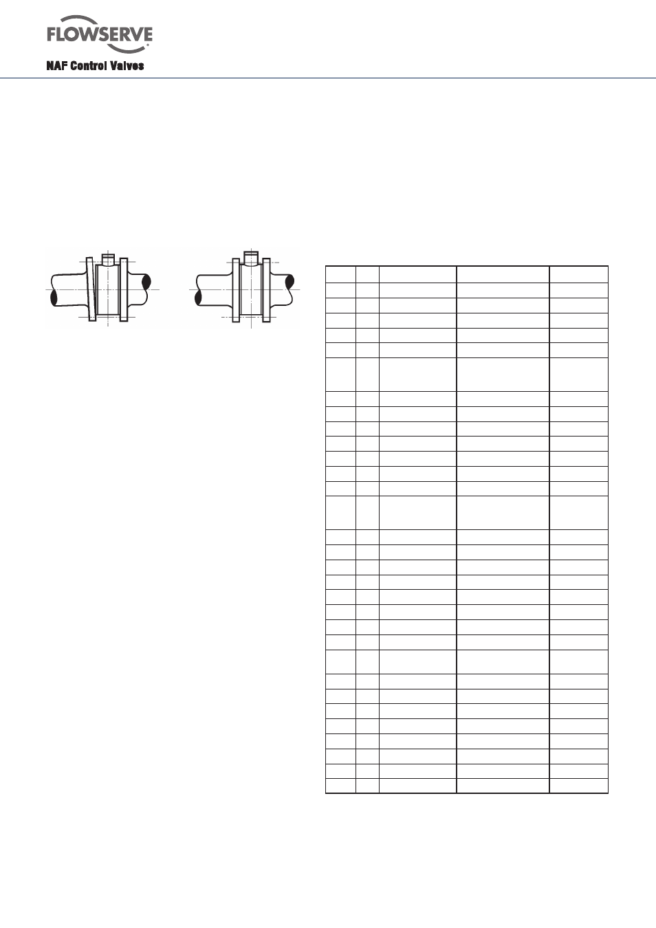
The valve must not be used for drawing together or alig-
ning incorrectly run pipes (see Fig. 2).
Wrong installation
Correct installation
Fig.2.
NAF-Torex valves can be installed in any position,
regardless of the direction of flow. However, we
recommend that, if installed in a horizontal run of pipe,
the valve should be mounted with the shafts horizontal,
in order to prevent the accumulation of dirt and other
impurities around the shaft ends.
The butterfly valve body is marked with an arrow which
indicates that best tightness thereby that the differential
pressure gives an additional torque in the closing
direction while a differential pressure towards the plane
side gives an extra torque in the opening direction.
Locate the valve so that it will be easily accessible
for inspection and service, particularly if the valve is
equipped with an actuator and a valve positioner.
Ensure that the valve is installed so that the connected
pipe ends do not obstruct the free movement of the disc
when the valve is operated.
The pipes should be supported on each side of the
butterfly valve, in order to relieve the valve of loads and
avoid vibrations.
5.
Flange gasket
Gaskets to the dimensions specified in SS 359, DIN 2690
or ANSI B 16.5, 1988, Table E1, Figure E2, Class 150 can
be used.
6.
Starting up
Before starting up, flush the pipework - with all valves
in the open position - so that any impurities that may
damage the sealing surfaces of the valve and impede its
operation will be flushed away.
For other information concerning starting up, see
”Instructions for valve positioners” Fi 41.82A.
Ensure that the pipe ends align and have the correct
distance
7.
List of materials and spare parts
Item Qty
Part
Material
Sealtype
1
1
Body
EN 1.4408/CF8M
2
1
Disc
EN 1.4408/CF8M
3
1
Gland cover
EN 1.4408/CF8M
4
1
Stem, upper
EN 1.4460
5
1
Stem, lower
EN 1.4460
6
1
Clamp ring
DN >250 EN1.4408/CF8M
DN<=250 EN1.4436/
AISI316
7
1
Retaining
EN1.4436
8*
1
Gasket
Graphite
9*
1
Gasket
Graphite
10*
1
Seat ring
Inconel 718
05-07,17
11*
1
Seat ring
EPDM
66
12*
1
Seat ring
FPM
55
14*
1
Seat ring
PTFE carbon reinforced
85,86,8A,8B
15*
1)
1
Clamp ring
DN >250 EN1.4408/CF8M
DN<=250 EN1.4436/
AISI316
16*
1
O-ring
EPDM
06,66,86
17*
1
O-ring
EPDM
06,66,86
18*
1
O-ring
FPM
05,55,85
19*
1
O-ring
FPM
05,55,85
20*
1
Backing ring
PTFE
21*
1
Boxpacking
Graphite
07,17
22
1
Cup spring
EN1.4310
0B, 8B
23
1
Gland cover
EN 1.4408/CF8M
24A
1
Boxpacking Zebra-
CL™
V-ring PTFE
0A, 8A
24B
1
Boxpacking Safeguard
V-ring PTFE liveloaded
0B,8B
26
1
Stem bearing
Metaloplast
27
1
Stem bearing
Metaloplast
28
2
Screw
A4
29
2
Nut
A4
30
2
Screw
A4
31
2)
Screw
A4
37
1
Washer
Metaloplast
1) Clamp ring item15 must be included if the valve is to be
converted from some other type of seat to a PTFE seat ring.
2) Quantity depending on dimension.
*) Recommended spare parts.
Other material combinations are available to order - consult your NAF representative.