Flowserve Torex butterfly valves User Manual
Naf-torex butterfly valves, Contents safety, Safety
1
Fi 41.42(4)GB
08.01
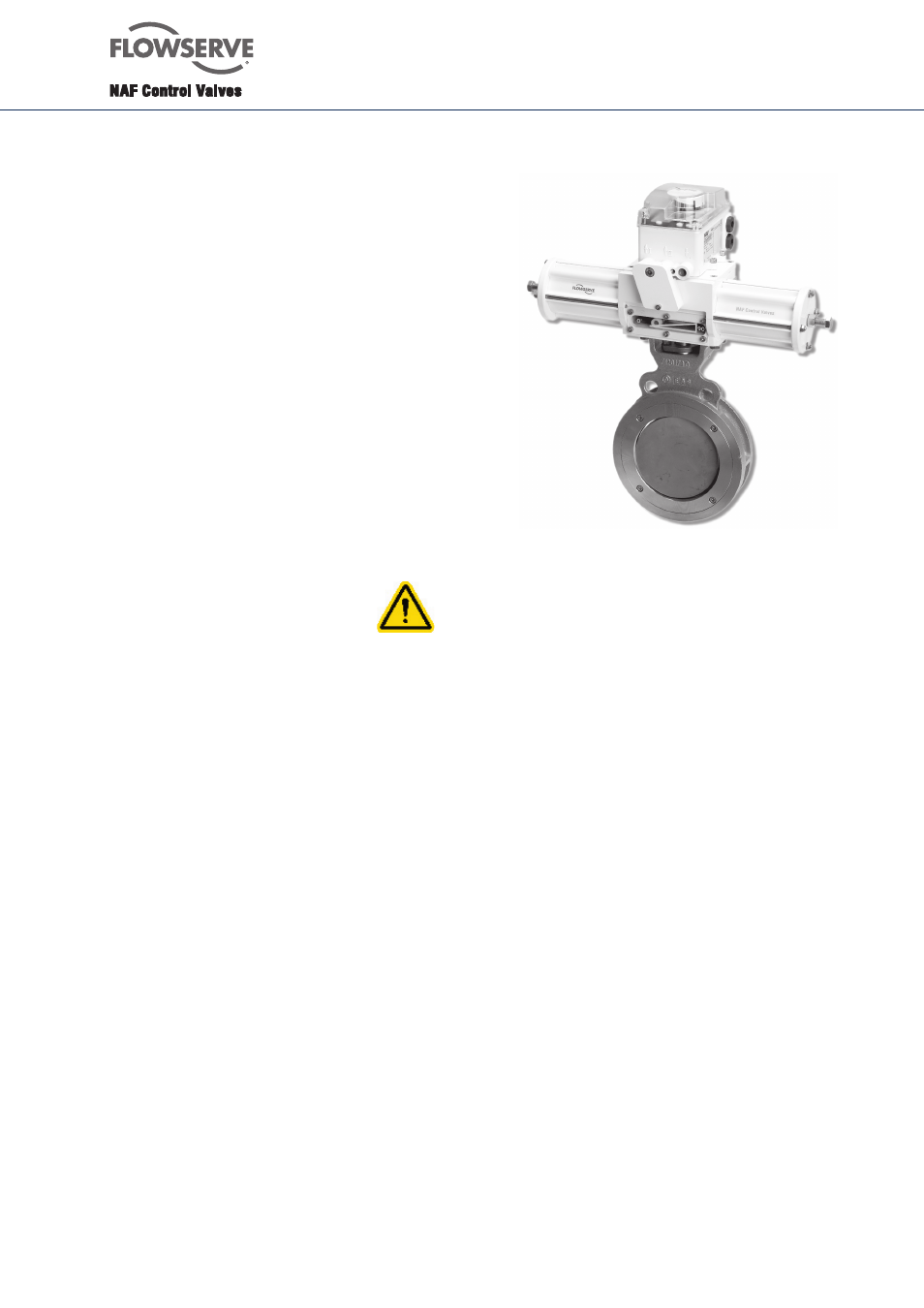
NAF-Torex butterfly valves
Maintenance and installation instructions
List of spare parts
Contents
SAFETY
General
1
Lifting
2
Receiving inspection
3
Installation
4
Flange gaskets
5
Starting up
6
List of materials and spare parts
7
Ordering of spare parts
8
Maintenance
9
To remove the valve from the pipework
9.1
To change an Inconel seat ring
9.2
To replace EPDM, FPM and PTFE seat rings
9.3
To replace PTFE seat rings
9.4
To adjust a new seat ring in a valve with
manual operating lever or worm gear unit
9.5
To adjust the seat ring in a valve with
pneumatic actuator
9.6
To change the upper shaft seal of O-ring type
9.7
To inspect and replace the upper shaft seal
of graphite type
9.8
To change the packing, item no. 9
9.9
To replace the shafts and valve disc
10
Fitting the actuator to the valve
11
SAFETY
- Assess all the risks to eliminate the risk of personal
injury and material damage. Read these instructions
thoroughly!
- Always use the necessary protective equipment
and comply with applicable safety directives when
working with hazardous or hot/cold medium.
- Never operate a valve without first ensuring that there
is no risk of crush injuries. The risk is highest with
automatic valves.
- Take necessary safety precautions to prevent
unintentional manoeuvre - i.e to atmosphere.
- Never dismantle a valve or part of a valve without
ensuring that the line is free of pressure and any
content.
- Always check that the valve type and material is
suitable for its intended use. This applies especially to
highly oxidising and corrosive medium. Observe also
the risk of erosion and explosion as well as decaying
medium. If in doubt, always request a written
recommendation from NAF AB.
1.
General
The instructions and list of spare parts in the
succeeding apply to NAF-Torex butterfly valves in
accordance with catalogue sheet Fk 41.42GB.
The product codes of NAF-Torex valves are as follows:
238ZBB - XXXX
- 05
238Z
BB - XXXX
- 06
238ZBB - XXXX
- 07
238Z
BB - XXXX
- 17
238Z
BB - XXXX
- 55 238Z
BB - XXXX
- 66
238Z
BB - XXXX
- 85 238Z
BB - XXXX
- 86
238Z
BB - XXXX
- 88
1)
Z = Pressure class
2)
XXXX = Size
3)
05 — 88 = Sealing type
2.
Lifting
All lifting must be carried out on the valve itself and not
on the actuator.
3.
Receiving inspection
All valves leaving our works are inspected and tested in
accordance with the relevant requirements or in accordan-
ce with the special provisions specified by the purchaser.
Valves equipped with actuators are subjected to
functional testing and are adjusted in such a manner that
every unit is completely ready for direct installation in the
pipework.
However, in view of damage that may have occurred
during transport, it is advisable that receiving inspection
be carried out as follows
- Check that the valve delivered is correct in terms of
type, size, equipment, etc.
- Examine the valve, actuator and valve positioner
regarding possible damages.
- Operate the valve to the limits of its travel to
check the settings of the limit stops.