Flowserve NT3000 Series User Manual
Page 10
NT 3000 Series Electro-Pneumatic Transducer Module FCD VLAIM0047-00 - 09/04
10
Service and Maintenance of the
Transducer Circuit Board
To replace the circuit board, refer to Figures 6 and 8 then proceed as
follows.
c
WARNING: The circuit board is an electrostatic sensitive
device. Use appropriate ESD protective devices when handling.
1. Disconnect air supply pressure to the positioner.
2. Remove the NT 3000 transducer housing cover (1).
c
WARNING: Disconnect power to the I/P transducer before
removing the housing cover in explosive atmospheres;
otherwise, personal injury may occur.
3. Disconnect the loop power electrical connections from the circuit
board (4).
4. Remove the three circuit board mounting screws (3) and carefully
pull the circuit board straight out of the housing.
5. Disconnect the pressure modulator (11) electrical connector from
the bottom of the circuit board.
6. If the plastic enclosure in the circuit board assembly (see Figure 8)
is separated, O-ring should be installed in the hole in the housing
base (position B), and not on the post on the bottom of the circuit
board (position A), prior to reassembling.
7. Reconnect the pressure modulator electrical connector to the circuit
board.
8. Reinstall the circuit board by engaging the pressure sensor tube
and pressing it straight into the housing. Be careful not to damage
the O-ring with the pressure sensor or pinch the modulator
connector wires while installing the circuit board. Apply thread
locking compound to the three circuit board mounting screws,
replace and tighten.
9. Reconnect the loop power electrical connections to the terminal
block noting polarity.
10. Reinstall the housing cover and reconnect the air supply pressure.
11. Check the span and zero calibration (see Calibration).
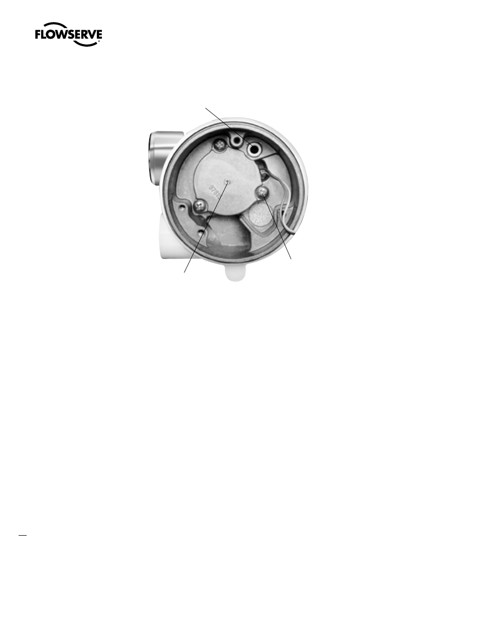
Figure 7 – NT 3000 Transducer Pressure Modulator (circuit board removed)
������������������
�����������������
���������
�����
��������
�����������