Flowserve Dual Gas Barrier Seals User Manual
Page 5
5
2.4 Position the seal with housing O-ring gasket in place against the
seal chamber face and tighten the gland nuts evenly in a diagonal
sequence. Do not over tighten the gland nuts.
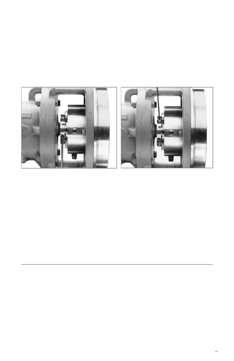
2.5 Using a cross-tightening method tighten the set screws on the
seal cartridge drive collar, Figure 6.
Tighten drive collar set screws
Figure 6
Remove setting devices
Figure 7
2.6 Remove setting devices by removing the screws with an Allen
wrench, Figure 7. Save the setting devices and screws for future
use in either removing the seal from service or to reset the pump
impeller, see section 5.
2.7 Turn the shaft by hand to ensure free operation.
2.8 Pipe up the gland connections to the seal, see section 3.
2.9 See Operational Recommendations, section 4, before
starting pump.
3
Piping
The Dual Gas Barrier Seal is designed to be operated in a normally dry
running mode with a pressurized clean inert gas (nitrogen) or air between
the two seals.
The gland is equipped with a gas barrier inlet and outlet connection.
3.1 Vent out the gas barrier line prior to connecting to the seal gland
to ensure that foreign material has not collected in the piping.