Flowserve Dual Gas Barrier Seals User Manual
Page 9
9
Dual Gas Barrier Seals - Installation and Mintenance Instructions for Machinery Components
6.2 Tighten the setting device cap
screws to ensure they are tight
before installation.
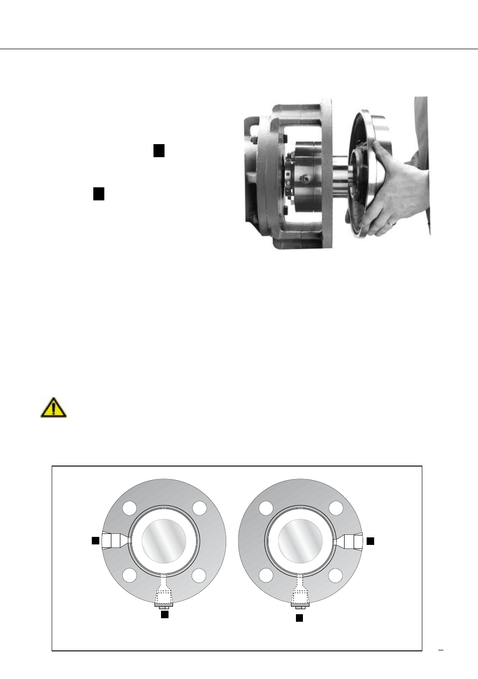
6. Install the pump seal chamber,
Figure 4. Position the seal gland
barrier inlet, port
A
shown in
Figure 5, in the 9:00 o’clock
position and the plugged drain,
port
B
, in the 6:00 o’clock posi-
tion for normal installations.
Alternate positioning of the gland
may be necessary with some
pumps, where the bearing
housing interferes with piping.
Bolt the seal chamber in place on the bearing housing.
6.4 Assemble the pump, adjust the bearings, set the impeller, connect pump
piping. Allow no pipe strain on the pump casing. Connect the coupling so that
the shaft is in its operating axial position.
6.5 Position the seal with housing O-ring gasket in place against the seal chamber
face and tighten the gland nuts evenly in a diagonal sequence. Do not over-
tighten the gland nuts, as this can warp seal parts and cause leakage.
Components provided by the customer for installing the mechanical seal, e.g.
the pump cover or fastening screws, must exhibit adequate properties and
Install pump seal chamber
Figure 4
A
Barrier
Inlet
Port
Drain
Port
B
A
B
Barrier
Inlet
Port
Drain
Port
Normal Installation
Position gland inle
t
Alternate Installation
Figure 5