Seal chamber requirements – Flowserve Dual Gas Barrier Seals User Manual
Page 7
7
Dual Gas Barrier Seals - Installation and Mintenance Instructions for Machinery Components
sleeve. Remove sharp edges from keyways and threads.
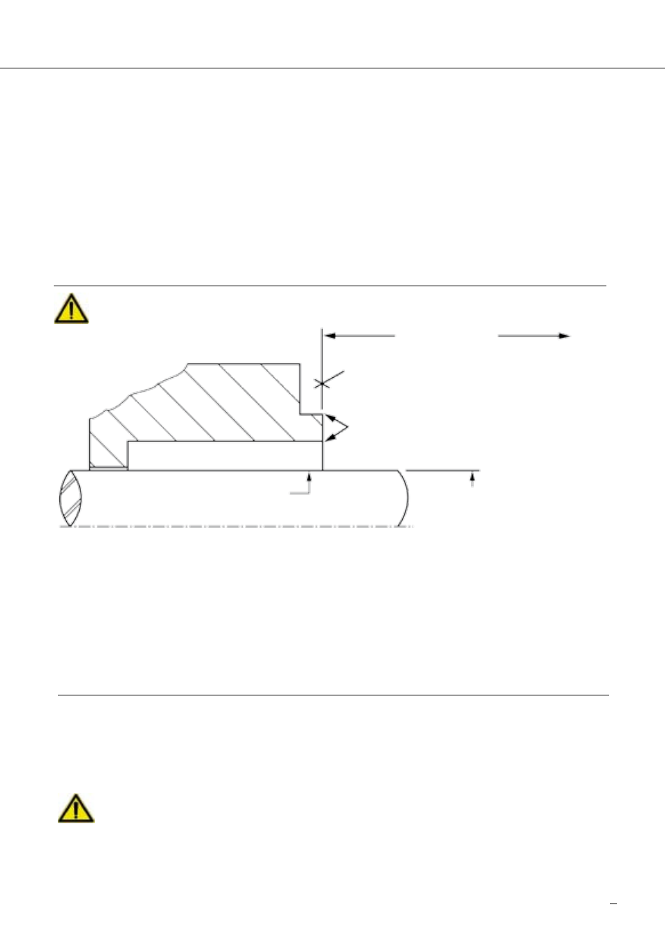
5.10 Check equipment requirements as described in Figure 1. Any reading
greater than what is allowed must be brought within specifications.
!
5.11 Handle the seal with care; it is manufactured to precise tolerances. The
seal faces are of special importance and should be kept perfectly clean at
all times. Oil, silicone lubrication, or type of grease should not be applied to
these seal faces.
6. Dual Gas Barrier Seal Installation
NOTE: No seal setting measurements are needed to install the seal. Instructions
are for end-suction back pull-out pumps. Modification of these procedures
may be required for other style pumps. Consult Flowserve for installation
support.
Take care that seal cartridge or components of the seal are handled and car-
ried safely during installation of mechanical seal and that the ergonomic prin-
ciples are followed. In order to prevent personal injuries the operator should
also wear protective clothing as per the plant’s safety regulations.
to first obstruction
Face of seal housing to be square to the axis of the
shaft to within 0.0005 inch (0.01 mm) FIM and have
√6-µ Inch (1.6 µm) Ra finish or better.
Gland pilot can be either of these register locations.
Concentric to within 0.005 inch (0.1 mm) FIM of
shaft or sleeve OD
Shaft or sleeve finish to be
2 µ inch (0.8 µm) Ra or better
Shaft or sleeve OD
+0,000 inch (+ 0,000 mm)
-0,002 inch (- 0,050 mm) ANSI
+0,000 inch (+0,000 mm) API 610
-0,001 inch (-0,025 mm) DIN / ISO
• Bearings must be in good condition.
• Maximum lateral or axial movement of shaft (end play) = 0.010 inch (0.25 mm) FIM
• Maximum shaft runout at face of seal housing = 0.002 inch (0.05 mm) FIM
• Maximum dynamic shaft deflection at seal housing = 0.002 inch (0.05 mm) FIM
Seal housing bore to have
√125 µ inch
(.2 µm) Ra or better
Seal Chamber Requirements
The mechanical seal may be installed when there are no visible signs of dam-
age to the mechanical seal. This applies in particular to the seats, centrings,
and the statically sealing 0-rings.
Figure 1