Flowserve CPM Supply Tank User Manual
Page 3
visual water flow indicator. However, when using API Plan 53/ANSI Plan
7353 the product must be able to accommodate a small amount of
contamination from the barrier fluid. Secondly, an API Plan 53/ANSI Plan
7353 system is dependent on having the supply tank pressure main-
tained at the proper level. If the supply tank pressure drops below seal
chamber pressure, seal leakage direction will be reversed and the barrier
fluid will be contaminated with the process fluid. The flush plan will then
become an API Plan 52/ANSI Plan 7352.
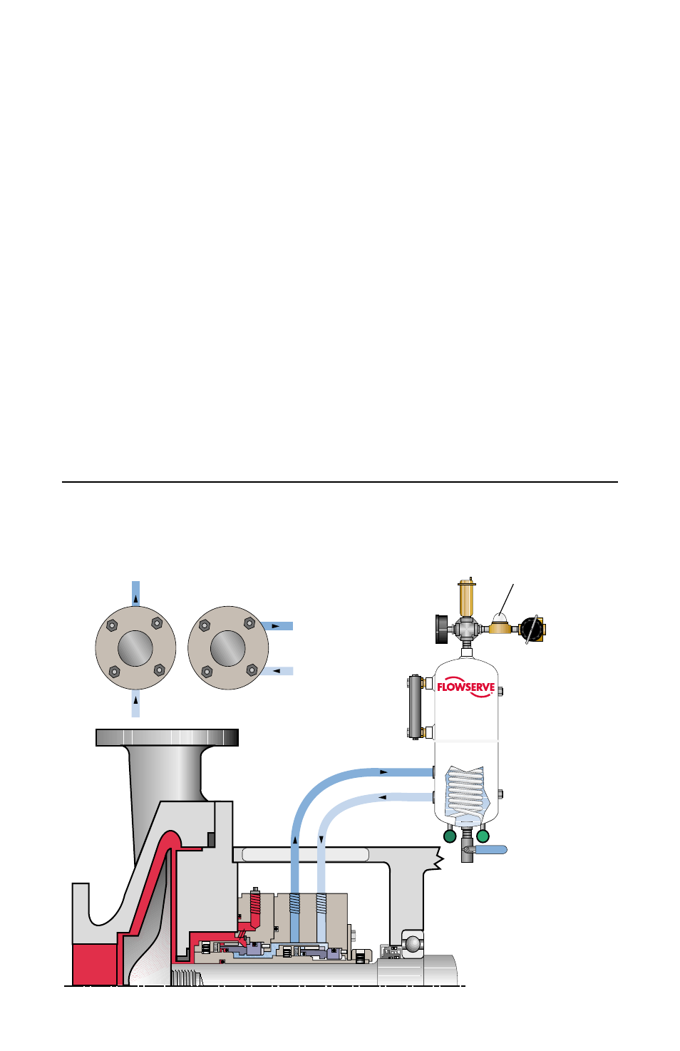
An Induced Circulation System is essentially the same as the thermal
convection system except for the addition of a circulating device in the
seal cavity which provides for positive flow in the system. The addition of
a circulating device provides for positive flow of buffer fluid shown in
Figure 1. To maximize dual seal cooling add cooling coils inside the
reservoir as a means of removing heat.
Dual Pressuzied Inside Seal with Induced Circulation
through CPM Seal Support Reservoir with Cooling Coil
Figure 1
Plan 53/ANSI Plan 7353
3
seal
end view
seal
end view
water
pressure
regulator
and inlet
port
visual water
flow indicator
drain
vent valve
cooling in
cooling out
304SS,
2 gallon
reservoir
inlet
level
gage
outlet
outlet
pressure
gage
inlet
vertical
porting
tangential
porting
or