Flowserve PSS II Durametallic User Manual
Page 4
4
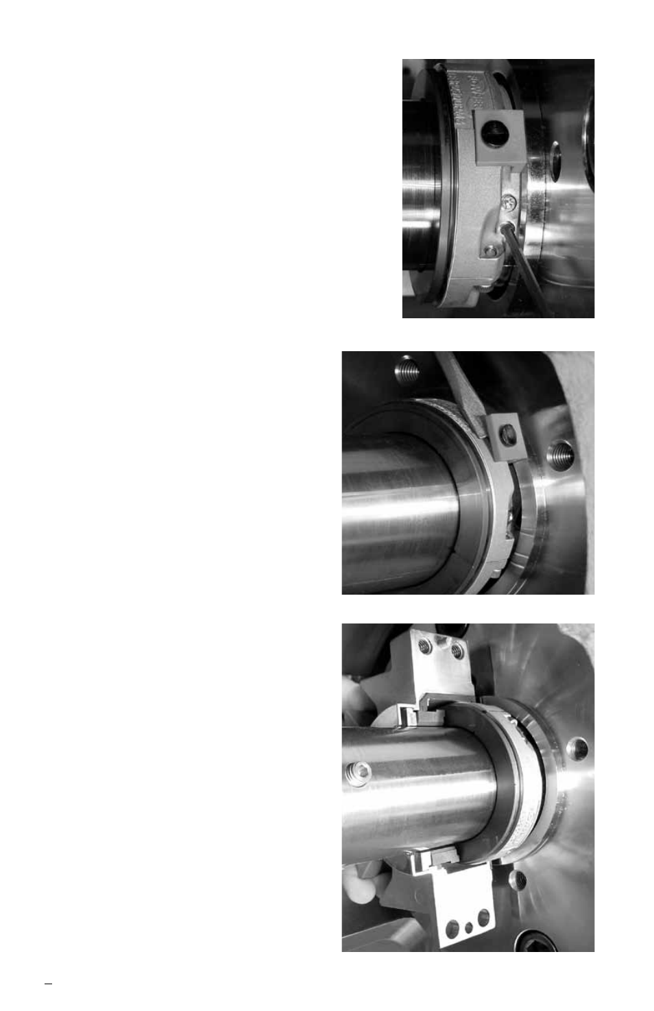
Step 4a With the setting devices against
the box face, tighten the set
screws. Seal sizes up to 101.6 mm
(4.000 inch) have four set screws
all at one joint while larger sizes
have an additional two set screws
at the opposite joint. Tighten all set
screws to 25 in-lbs for seal sizes
up 50.8 mm to (2.000 inch) and
50 in-lbs for larger sizes. For seal
sizes above 152.4 mm (6.000 inch),
refer to seal assembly drawing for
number of set screws and torque
specifications.
b Tighten set screws a second
time
in the same succession.
Step 5 Pry off the seal drive setting
devices
with a screwdriver.
Step 6a Lubricate the seat gasket ends
and exposed surfaces of the
gland split joint gaskets with the
enclosed lube.
b Carefully assemble the gland
halves around the rotor.
c Finger tighten the gland cap
screws. There should be a gap
between the halves of about
0.8 mm (.03 inch).
d Finger tighten the gland bolts so
the gland is supported at the
pump mounting surface while
the cap screws are being
tightened.
e Tighten the gland cap screws
to 12 ft-lbs minimum.
f Tighten the gland mounting
bolts evenly until the gland
gasket is fully compressed and
the gland is squarely seated
against the pump box face. This is
approximately 25 ft-lbs torque.
Step 4
Step 5
Step 6