Seal reference, Figure 1, Seal chamber requirements figure 2 – Flowserve PSS II Durametallic User Manual
Page 2
While the PSS II has been designed for rugged industrial application and
ease of installation, it does require assembly in a clean environment
according to the following installation steps. No setting dimensions or
measurements are required to install the seal.
2
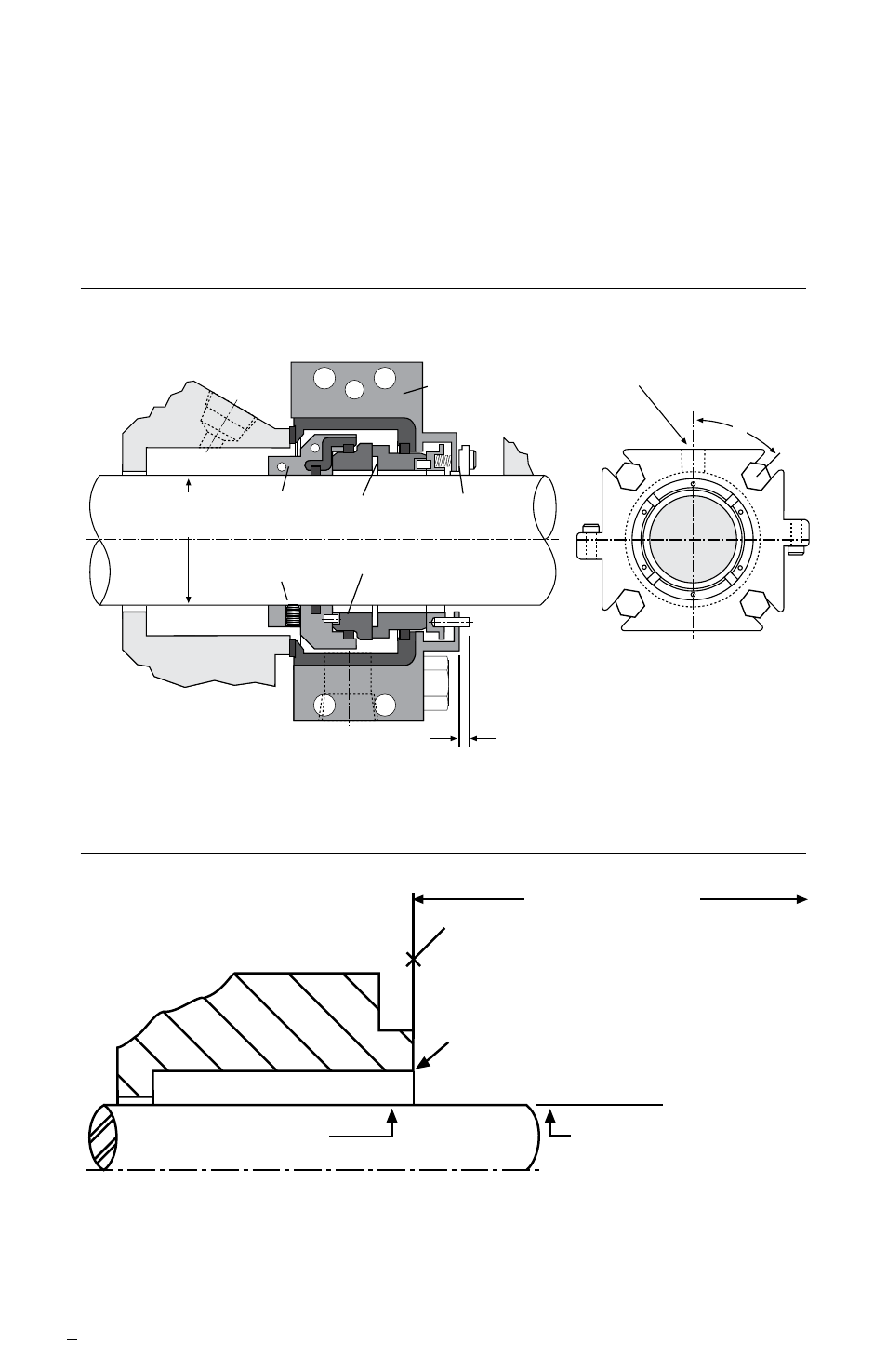
Seal Reference
Figure 1
Shaft and
Seal Size
Seal
Drive
Stationary
Face
Centering
Device
Set
Screw
Rotating
Face
4.8 mm (.19 inches) maximum
2.5 mm (10 inches) minimum
Pin Extension
1 - NPT
for Flushing
Gland
Seal Chamber Requirements Figure 2
To first obstruction
Face of seal housing to be square to the axis
of the shaft to within 0.015 inches per inch of
seal chamber bore (0.38 mm) FIM and have a
√
63
μ
inch (1.6
μ
m) R finish or better
a
Concentric to within 0.015 inch (0.38 mm) FIM
of shaft or sleeve OD
Seal housing bore to have √125 μinch
(3.2 μm) R finish or better
Sleeve or shaft finish to be
32 μinch (0.8 μm) R or better
a
a
Shaft or sleeve OD
+0.001 inch (+0.025 mm)
-0.002 inch (-0.050 mm) ANSI
• Bearings must be in good condition
• Maximum lateral or axial movement of shaft (end play) = 0.010 inch (0.25 mm) FIM
• Maximum shaft runout at face of seal housing = 0.004 inch (0.10 mm) FIM
• Maximum dynamic shaft deflection at seal housing = 0.002 inch (0.05 mm) FIM
45°
The images of parts shown in these instructions may differ visually from the actual
parts due to manufacturing processes that do not affect the part function or quality.