6 completing installation, Cartridge in place (dry side) figure 14 – Flowserve SLM-6200 User Manual
Page 9
9
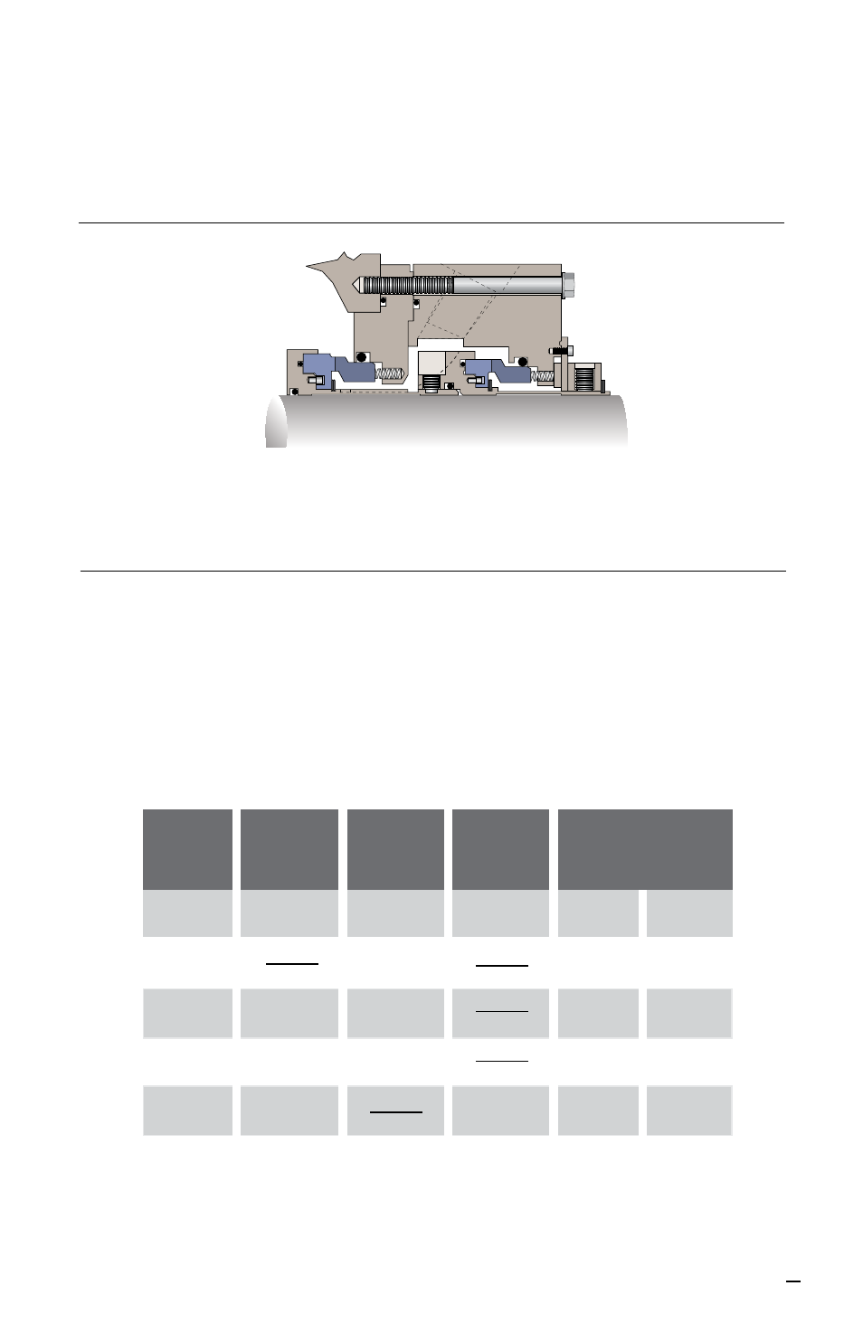
5.9 Slide the seal cartridge up to the equipment case. Insert the gland retaining bolts
through the gland holes and screw into the threaded holes on the face of the
equipment case. Tighten the retaining bolts evenly in opposing pairs. See Figure 14.
6 Completing Installation
6.1 Evenly tighten the Socket Head Cap Screws of the 2-piece split clamp collar, the Hex
Head Cap Screws of the 3-piece shrink disk collar, or the Set Screws of the 1-piece
sleeve collar to the proper torque values listed below.
Cartridge in Place (Dry Side) Figure 14
TORQUE VALUES
N-m
(ft-lbs)
Split Clamp Shrink Disk Set Screw Set Screw Penetrating
Clamp
Clamping
(Cup Point)
(Dog Point)
Fastener Alloy Steel Alloy Steel Alloy Steel Stainless Alloy
Size
Steel Steel
1/4”
14-16
5-8 9-11
(10-12)
(4-6) (7-8)
5/16” 33-35 27-30
14-16 18-20
(24-26) (20-22)
(10-12) (13-15)
3/8” 54-61 33-37
24-27 30-34
(40-45) (24-27)
(18-20) (22-25)
1/2” 122-136
68-75 54-57 81-84
(90-100) (50-55)
(40-42)
(60-62)