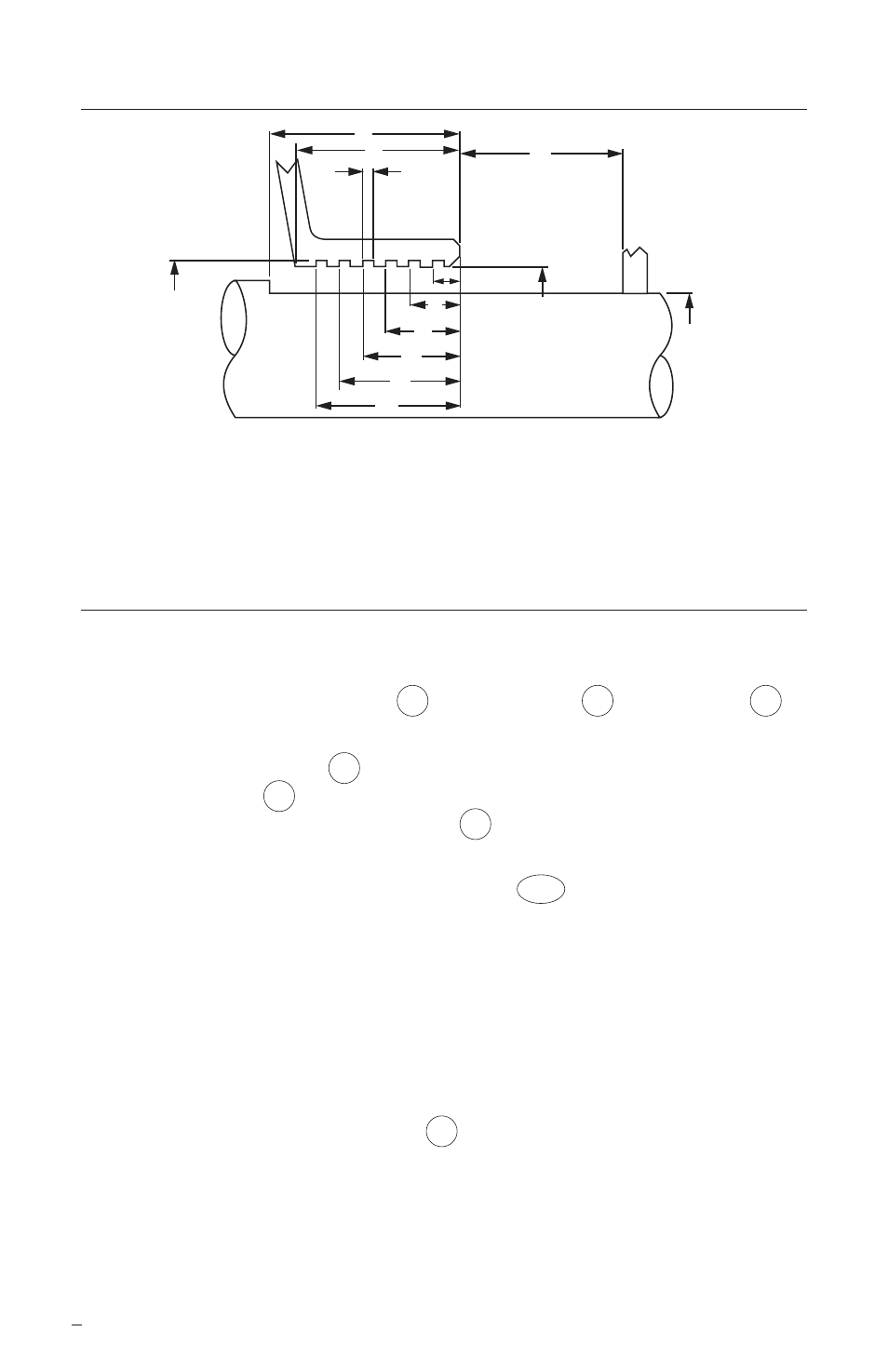
5 installation of seal (method 1), Seal chamber requirements figure 1 – Flowserve GTS Series User Manual
Page 6
6
5 Installation of Seal (Method 1)
5.1 Remove the seal assemblies from the box. Inspect for any obvious signs of
mishandling or damage.
5.2 Set aside the sleeve gaskets 19 , flange gaskets 18 , and lock pins 5
for installation later.
5.3 Spin the spanner nuts 9 until there is a .375 inch gap between the
retaining rings 54 and the flange shoulders. This simulates the installation
of the .375 inch wide flange gaskets 18 .
5.4 Lower the seal assemblies into the proper grooves in the turbine casing per
the assembly drawing. The setting devices 103 should be oriented at the
12 O'clock position. Lower the bearing caps into place to insure proper fit
of the assemblies. The spanner nuts should not interfere with the bearing
caps.
5.5 The seals should seat fully in the turbine case. If they do not, the turbine will
not seal at the split line. Measure the turbine bore diameters and the seal
OD diameters to ensure adequate clearance. Compare with the information
on the assembly drawing.
5.6 Mark the location of the lock pins 5 . These lock pins will prevent the seal
flanges from rotating in the turbine casing. A small slot must be milled or
ground into the casing for each pin so that the pins do not interfere with the
lowering of the top half of the casing. The slots should not be any larger
than necessary to contain the pins and should not break into the adjacent
gasket sealing areas.
F6
F5
F4
F3
F2
F1
F7
O
D
F8
A
B
F
A
Turbine Bore
F2 Groove Location
F7 Groove Width
B
Shaft Step to Box Face F3 Groove Location
F8 Groove Depth Diameter
D
Shaft Diameter
F4 Groove Location
O First Obstruction
F
Turbine Depth
F5 Groove Location
F1 Groove Location
F6 Groove Location
Seal Chamber Requirements
Figure 1