Flowserve ISC2 Single Pusher Repair User Manual
Page 5
5
For sizes
≤ 2.750 inch (70 mm) install the vibration damper [183] into the
back counterbore of the sleeve assembly.
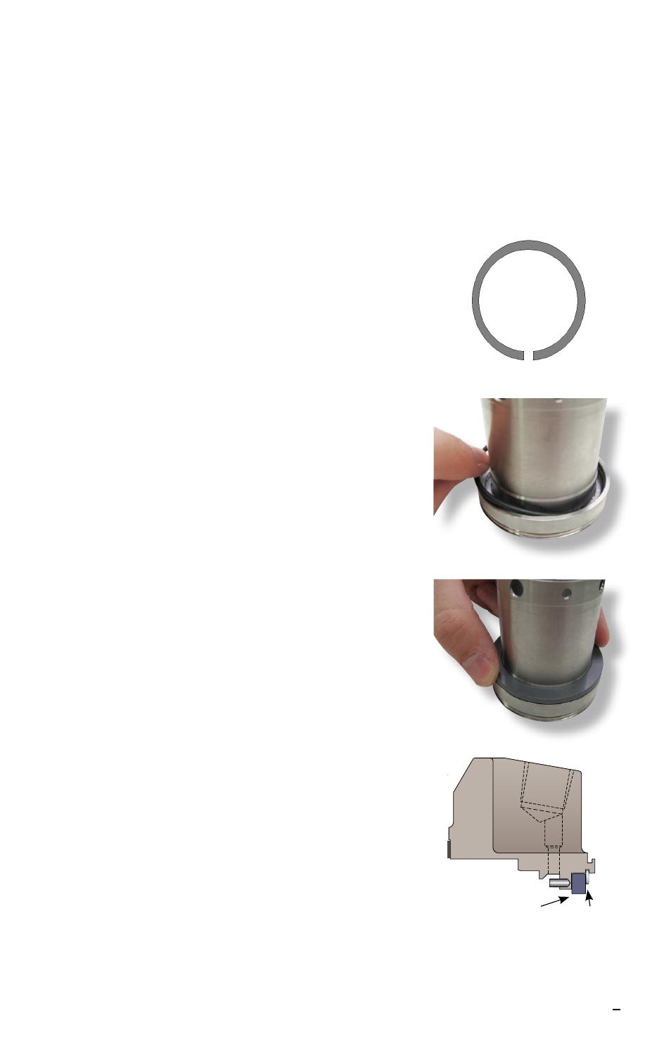
For sizes > 2.750 inch (70 mm)
install the square-headed pin [5] in the hole
on the counterbore of the sleeve assembly. Cut a 0.25 inch (6 mm) slot in
the vibration dampener [183] and install onto the sleeve assembly where
the rotating face will be installed with the slot positioned where the drive pin
is located. See Figure 7.
6.3 Select O-ring [19] and stretch slightly. Lightly lubricate the O-ring using
silicone grease.
For sizes
≤ 2.750 inch (70 mm) install the O-ring
into the sleeve assembly, on the inner diameter
groove of the sleeve. See Figure 8.
For sizes > 2.750 inch (70 mm)
install the O-ring
into the inner diameter groove of the bellows
assembly.
6.4 Select rotating face [15] and lightly lubricate
O-ring surface using silicone grease unless
otherwise specified. Install the rotating face [15]
into the sleeve/O-ring assembly. See Figure 9.
Use hand pressure only.
For sizes ≤ 2.750 inch (70 mm)
ensure that the
flats on the rotating face and the flats on the
sleeve are aligned.
For sizes > 2.750 inch (70 mm)
ensure that the
drive slot on the rotating face and the square-
headed drive pin in the sleeve are aligned.
6.5 Check for the proper seating of the rotating
face by measuring from the back of the sleeve
assembly to the face of the rotating face with
a caliper or micrometer. Measure in 3 equally
spaced locations, measurement variations
should not exceed 0.005 inch (0.127 mm).
6.6 Clean the sealing face of the rotating face [15]
to remove dirt, dust, fingerprints or any other
residue using alcohol on a clean cloth or tissue.
6.7 Select gland assembly [11] and using a parallel-
plate press, press bushing [24] into the outboard
side of the gland. Once the bushing is fully
pressed in the gland assembly [11] (no gap
behind bushing), insert the snap ring [111] into
the groove on the inner diameter of the gland to
retain the bushing as shown in Figure 10.
Figure 8
Figure 9
Figure 10
[24]
[111]
Figure 7