Tac‐4 installation instructions – FiberPlex EF2 User Manual
Page 14
Led indicators
Label
Color
Description
Power
PWR
Green
Power supply is operating properly.
Off
Check that the 1 Amp Slo‐Blo fuse is not blown.
Ethernet
TP Link
Yellow
10BASE‐T twisted pair link has been established.
Green
100BASE‐TX twisted pair link has been established.
Off
No twisted pair link pulses detected.
Aviom’s Personal Mixers do not transmit link pulses for the EF‐2 to detect. Therefore this LED will always be off. For
link indication, Aviom’s Personal Mixers have an LED labeled “A‐NET Active”.
TP RX
Yellow
Twisted pair receive data is being detected.
Optical
Link
Yellow
10BASE‐FL optical link has been established.
Green
100BASE‐FX optical link has been established.
Off
No optical link pulses detected or optical level too low. Check that the opposite unit has power and that the fiber optic
cables are properly connected. The transmit output from one end should go to the receive input at the opposite end.
Or switch setting is in the OPT TX position, which is a uni‐directional mode where data can only be received by the RJ‐
45 and transmitted to the fiber optic output. Therefore, optical link pulses can not be received by the fiber optic input.
OPT RX
Yellow
Optical receive data is being detected.
Off
No optical receive data detected.
Or switch setting is in the OPT TX position, which is a uni‐directional mode where data can only be received by the RJ‐
45 and transmitted to the fiber optic output. Therefore, optical data can not be received by the fiber optic input.
TAC‐4 Installation Instructions
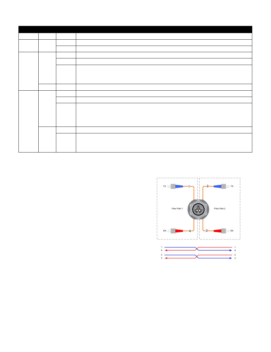
When using TAC‐4 panel mount connectors:
Due to the hermaphroditic nature of the TAC‐4 connector, channels 1 & 4 and
2 & 3 are crossed by necessity. Therefore, pins 1 & 2 should always be
connected to connectors marked TX and pins 3 & 4 should always be
connected to pins marked RX. Pins 1 & 4 are always paired together and pins 2
& 3 will always be paired together.
Important Note: A single TAC‐4 connector and cable contains (4) fibers and
can transport both pairs of fiber inputs/outputs of the EF‐2 on a single
connector / cable. If using Neutrik OpticalCon, two cables / connectors are
required, one for each pair, as the OpticalCon cable and connectors contain
(2) fibers. When using LC or ST fiber connectors on the chassis of the EF‐2, the
connectors are mounted on the rear of the unit. Alternatively these fiber
connectors can be mounted on the front panel of the unit.