Digi-Star John Deere 1990 30 & 36 CCS 1690 Version User Manual
Page 5
Scale Bracket and Load Cell Mounting Installation
D3864-US-Rev A
John Deere Planter Scale
3
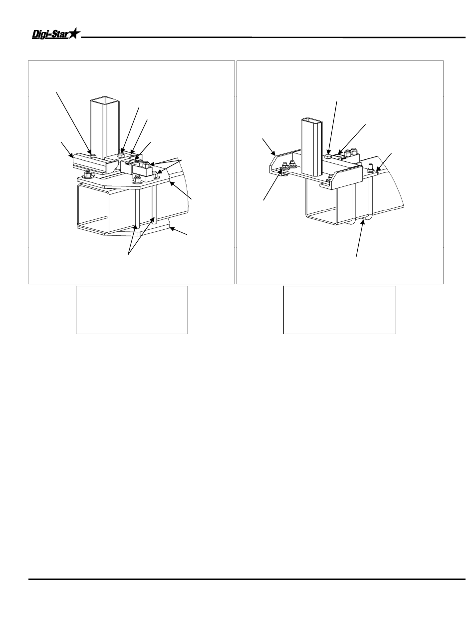
Use Figures 2 and 3 for steps 9 - 13
9. Install the front top bracket by using the 5/8 x 3 1/2” special bolts. The cropped bolt edge is installed next to
the 4 x 4 tubing and from the top (see Figure 2). Install the front top bracket by using 5/8 x 2” bolt and washer,
flange nut (see Figure 3).
10. Assemble load cell to the front base plate by using 3/4 x 3 1/2 in. bolts and locknut. Do not tighten bolts
completely. You may have to slide load cell while aligning base and top brackets.
TOP DECAL NEEDS TO
BE ON TOP OF LOAD CELL!
(See Figure 2 or 3)
11. Install front base plate weldment to the main frame with the yoke plate on the bottom. Reuse the original
frame bolt (see Figure 2). Install front base plate weldment to the main frame with the supplied 5/8 x 8.75” U-
bolts and 5/8 top lock flange nuts (see Figure 3).
12. The load cell is held to the front top bracket with 3/4 x by 2 in. bolts. The 2 in. bolts need to have thread
lock applied to the threads.
THIS BOLT CAN NOT BE COMPLETELY TIGHTENED DOWN, LEAVE 1/16 in.
BETWEEN BOTTOM OF BOLT HEAD AND TOP BRACKET!
13. Install brackets on the other front leg. When all brackets are installed tighten all of the frame bolts, top
brackets and load cell bolt.
Figure 3
Front Leg Assembly
JD 1990 Single 40’ & 44’
(Right Side Shown)
Figure 2
Front Leg Assembly
JD 1990 Single 30’
(Left Side Shown)
5/8” Top Locking Flange Nut
and 5/8 x 8.75” U-Bolts
Rear Base
Plate
Load Cell
(Decal on Top Side)
3/4” x 3.5” Fine
Threaded
(See Detail A)
Load Cell (Decal
on top side)
Reuse
Front Yoke
Plate
Reuse Frame Plates and
5/8” Frame Bolts
Top Bracket
5/8” x 3-1/2” special
bolt and 5/8 flange
Front Top
Bracket
3/4” x 2” Fine Threaded
(See Detail A)
3/4 x 3-1/2”
bolts and 3/4”
Locknuts
Front Base
Plate
Front Top
Bracket
5/8” x 2” bolt,
5/8 Flat Washer,
5/8 Top-Lock
Flange Nut