Chapter 2 – DFI HD101-H81 User Manual
Page 20
www.dfi .com
20
Chapter 2 Hardware Installation
Chapter 2
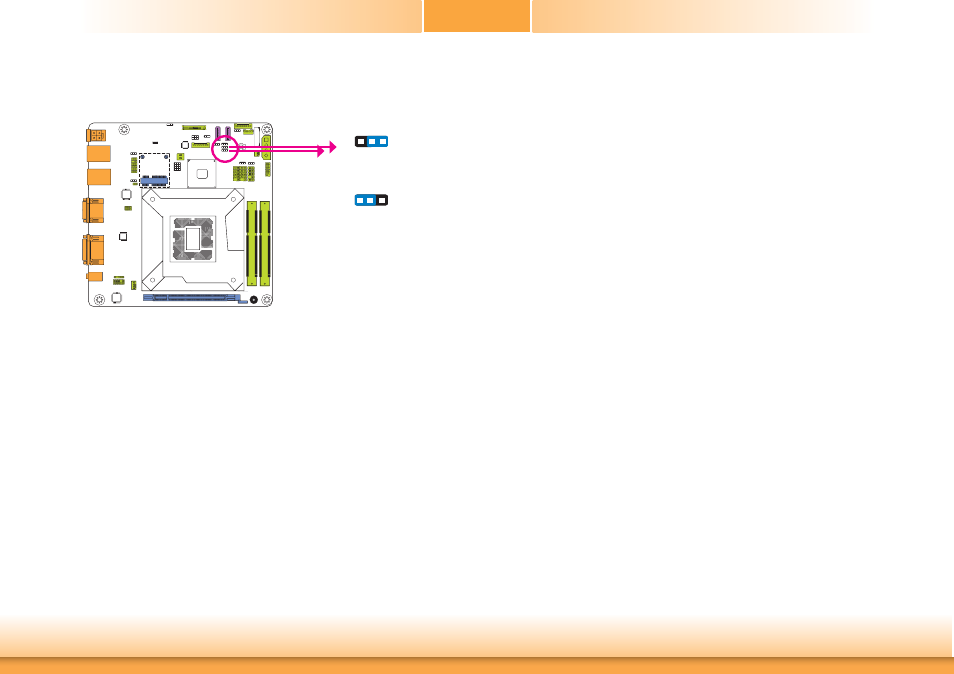
Digital I/O Output State
3
1
2
3
1
2
DIO 0-3
(JP16)
DIO 4-7
(JP17)
1-2 On: +5V or
+5V_standby
(default)
2-3 On: GND
Based on the power level of DIO (Digital I/O) selected on JP15, JP16 (DIO pin 0-3) and JP17
(DIO pin 4-7) are used to select the output state of Digital I/O: pull high or pull low. When
selecting pull high, the power selection will be the same as JP15’s setting.
See also other documents in the category DFI Motherboard:
- AR100-DR (112 pages)
- G7B630-N (127 pages)
- G7B630-N (154 pages)
- BT100 (71 pages)
- HR100-CRM (170 pages)
- BT103 (72 pages)
- BT161 (71 pages)
- CM100-C (70 pages)
- CD101-N (69 pages)
- CD102 Series (76 pages)
- CP100-NRM (150 pages)
- CR101-D (67 pages)
- CR100-CRM (177 pages)
- EL339-B (109 pages)
- G5C100-NR (160 pages)
- HD100-H81 (79 pages)
- HD173-H81 (70 pages)
- HM100-QM87 (97 pages)
- HM103-QM87 (99 pages)
- HU103 (95 pages)
- KB161 (68 pages)
- HU173 (90 pages)
- LR100-N18M/N18S (126 pages)
- LR102-B18M (138 pages)
- EL630-NR (149 pages)
- NP101-D16C (150 pages)
- SB102-D (60 pages)
- NP102-N16C (144 pages)
- MB630-CRM (171 pages)
- SB630-CRM (184 pages)
- SB630-CRM (183 pages)
- SR100-L20C (144 pages)
- SR100-N (152 pages)
- LT600-L (149 pages)
- G7B630-N (147 pages)
- CA331-P (131 pages)
- EL330-DR (142 pages)
- CP337-NRM (174 pages)
- HD310-Q87 (101 pages)
- EL620-C (192 pages)
- G7L630-B (133 pages)
- HD330-H81 (81 pages)
- HD330-Q87 (85 pages)
- HD332-H81 (76 pages)