DFI CR100-CRM User Manual
Page 22
22
2
Hardware Installation
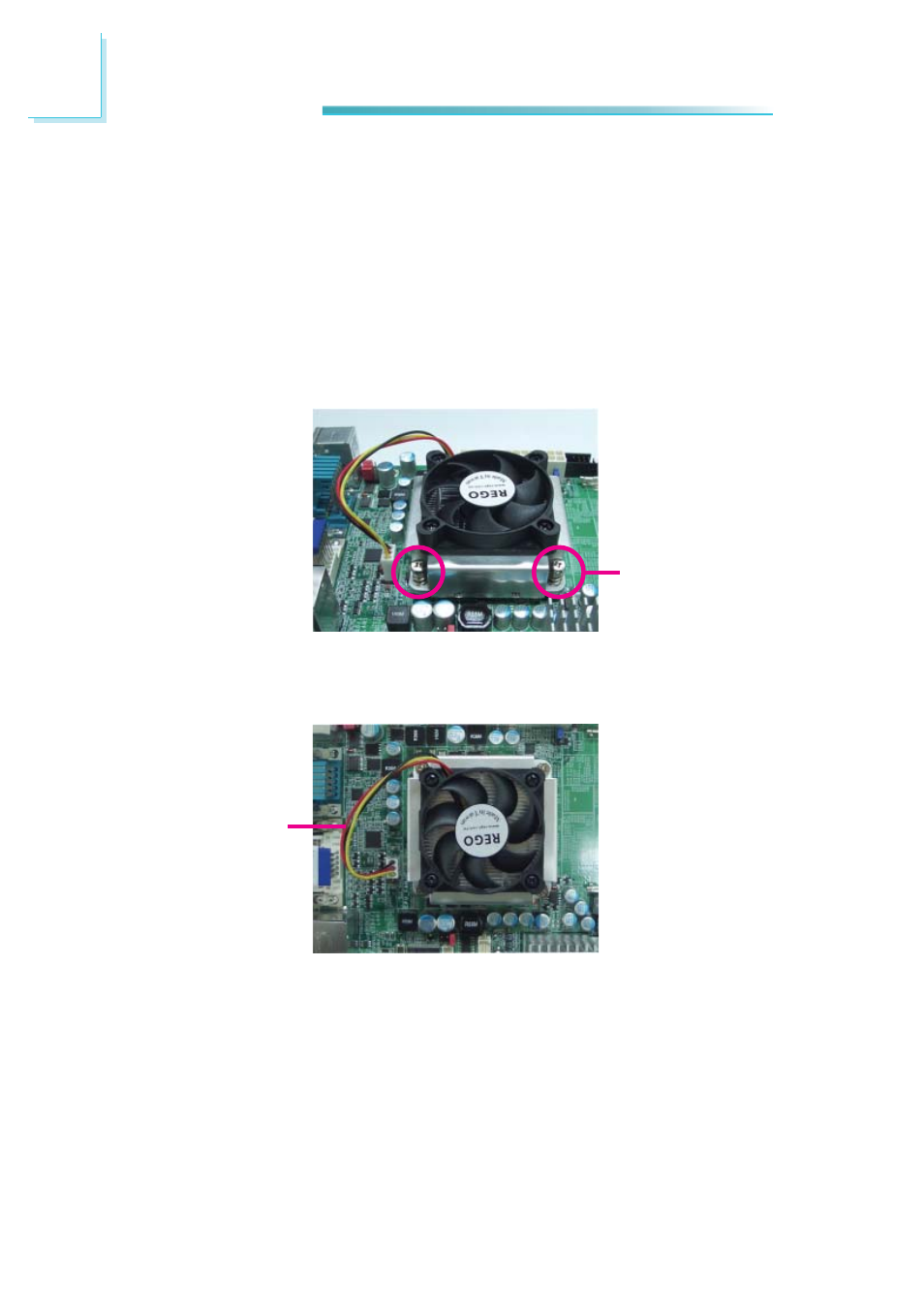
5. Connect the CPU fan’s cable connector to the CPU fan connector on the sys-
tem board.
Mounting
screw
4. Place the fan / heat sink assembly on top of the CPU. The 4 screws around
the heat sink must match the screw holes of the retention module base. We
strongly recommend using this type of fan / heat sink assembly because it
provides adequate cooling to the components of the system board.
Turn each Phillips head screw half way down fi rst to initially stabilize the heat
sink onto the board, then fi nally tighten each screw.
Important:
Do not turn the fi rst screw all the way down followed by the next and so on.
This is to avoid imbalance which might cause cracks or fractures to the CPU
and/or heat sink assembly.
CPU fan cable
- AR100-DR (112 pages)
- G7B630-N (127 pages)
- G7B630-N (154 pages)
- BT100 (71 pages)
- HR100-CRM (170 pages)
- BT103 (72 pages)
- BT161 (71 pages)
- CM100-C (70 pages)
- CD101-N (69 pages)
- CD102 Series (76 pages)
- CP100-NRM (150 pages)
- CR101-D (67 pages)
- EL339-B (109 pages)
- G5C100-NR (160 pages)
- HD100-H81 (79 pages)
- HD101-H81 (83 pages)
- HD173-H81 (70 pages)
- HM100-QM87 (97 pages)
- HM103-QM87 (99 pages)
- HU103 (95 pages)
- KB161 (68 pages)
- HU173 (90 pages)
- LR100-N18M/N18S (126 pages)
- LR102-B18M (138 pages)
- EL630-NR (149 pages)
- NP101-D16C (150 pages)
- SB102-D (60 pages)
- NP102-N16C (144 pages)
- MB630-CRM (171 pages)
- SB630-CRM (184 pages)
- SB630-CRM (183 pages)
- SR100-L20C (144 pages)
- SR100-N (152 pages)
- LT600-L (149 pages)
- G7B630-N (147 pages)
- CA331-P (131 pages)
- EL330-DR (142 pages)
- CP337-NRM (174 pages)
- HD310-Q87 (101 pages)
- EL620-C (192 pages)
- G7L630-B (133 pages)
- HD330-H81 (81 pages)
- HD330-Q87 (85 pages)
- HD332-H81 (76 pages)