Standby power led, Cooling option, Chapter 3 standby power led – DFI HM960-HM86 User Manual
Page 27
www.dfi .com
Chapter 3 Hardware Installation
27
Chapter 3
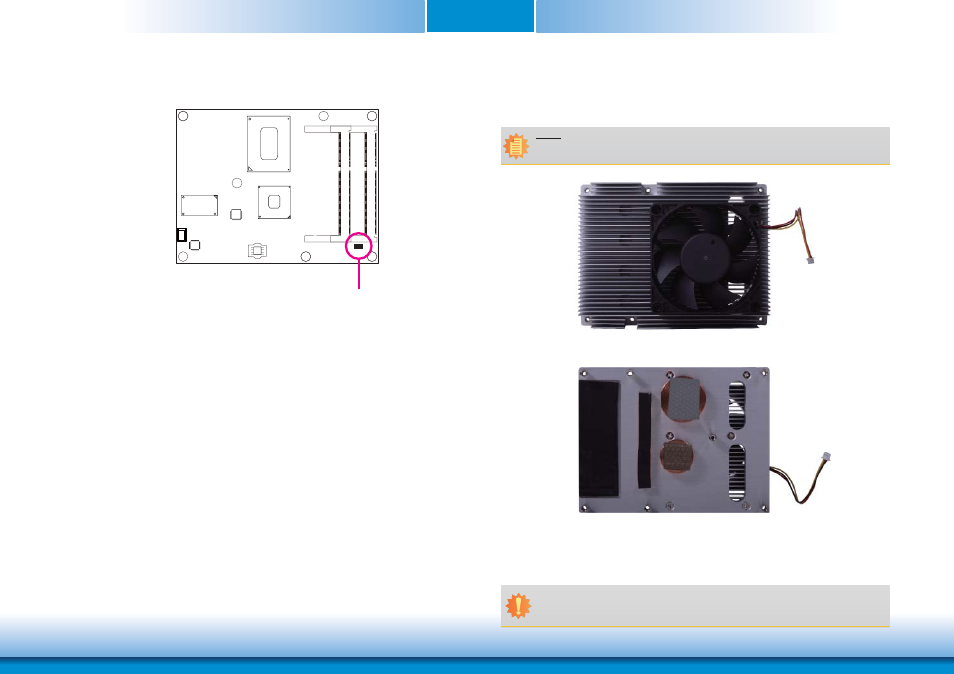
Standby Power LED
Standby
Power LED
This LED will light when the system is in the standby mode.
Cooling Option
Heat Spreader with Heat Sink and Fan
• “1” and “2” denote the locations of the thermal
pads designed to contact the corresponding compo-
nents that are on HM960-QM87/HM86.
Important:
Remove the plastic covering from the thermal pads prior to mounting the heat sink
onto HM960-QM87/HM86.
Note:
The system board used in the following illustrations may not resemble the actual
board. These illustrations are for reference only.
Top View of the Heat Sink
Bottom View of the Heat Sink
1
2
This manual is related to the following products: