Chapter 3 cpu – DFI CM901-B User Manual
Page 14
www.dfi.com
Chapter 3 Hardware Installation
14
Chapter 3
CPU
Overview
The system board is equipped with a surface mount rPGA 988B CPU socket.
Installing the CPU
1. Make sure the PC and all other peripheral devices connected to it has been powered down.
2. Disconnect all power cords and cables.
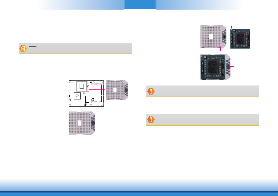
3. Locate the FS1r2 (722-pin lidless
micro PGA) socket on the board.
4. Make sure the screw is in its
unlock position. If it’s not, use a
screwdriver to turn the screw to
its unlock position.
Screw in unlocked
position
5. Position the CPU above the socket.
The gold triangular mark on the
CPU must align with pin 1 of the
CPU socket.
Pin 1
Gold triangular mark
6. Insert the CPU into the socket until it is seated in place. The CPU will fit in only one
orientation and can easily be inserted without exerting any force. Use a screwdriver to turn
the screw to its lock position.
Screw in locked
position
Note:
The system board used in the following illustrations may not resemble the actual
board. These illustrations are for reference only.
Important:
Handle the CPU by its edges and avoid touching the pins.
Important:
Do not force the CPU into the socket. Forcing the CPU into the socket may bend the
pins and damage the CPU.