Chapter 3 – DFI CD905-B2800 User Manual
Page 31
www.dfi .com
Chapter 3 Hardware Installation
31
Chapter 3
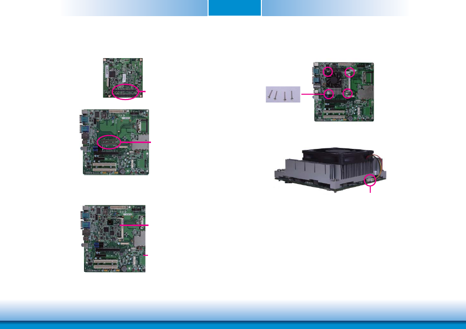
6. Grasping CD905-B by its edges, position it on top of the carrier board with its mounting
holes aligned with the bolts on the carrier board. This will also align the COM Express
connectors of the two boards to each other.
COM Express connec-
tors on CD905-B
COM Express connectors
on the carrier board
Carrier board
7. Press CD905-B down firmly until it is completely seated on the COM Express connectors of
the carrier board.
CD905-B
8. Use the provided mounting screws to secure CD905-B with heat sink to the carrier board
and then connect the cooling fan’s cable to the fan connector on CD905-B.
The photo below shows the locations of the long mounting screws.
Long screws
Fan connector
9. And then connect the cooling fan’s cable to the fan connector on CD905-B.
- ES300 (2 pages)
- U340 Series (2 pages)
- VS Series (2 pages)
- BT9A3 (57 pages)
- CD9A3 series (60 pages)
- CD905-B series (68 pages)
- BT700 (71 pages)
- BT700 (71 pages)
- CD905-B2600 (63 pages)
- CP908-B (104 pages)
- CR908-B (68 pages)
- HR908-B (66 pages)
- HU968 (86 pages)
- ML905-B11C/B16C (76 pages)
- KB968 (68 pages)
- LR905-B18S (93 pages)
- OT905-B series (61 pages)
- CM960-B (1 page)
- CM901-B (72 pages)
- CP900-B (130 pages)
- NP905-B16C (125 pages)
- CR900-B (73 pages)
- CR902-BL (75 pages)
- CR901-B (69 pages)
- CR960-QM77 (81 pages)
- HM920-QM87 (98 pages)
- G5C900-B106 (118 pages)
- HM960-QM87 (101 pages)
- HM961-QM87 (95 pages)
- HR900-B (102 pages)
- HR902-BL (75 pages)
- FS700 (17 pages)
- QB702-B (47 pages)
- QB700-B (73 pages)
- COM100-B (32 pages)
- QB701-B (73 pages)
- NP900-B16C (121 pages)
- COM101-BAT (32 pages)
- COM630-B (50 pages)
- COM330-B (57 pages)
- Q7-100 (31 pages)
- Q7-951 (46 pages)
- Q7A-551 (23 pages)
- Q7X-151 (30 pages)