Chapter 3 – DFI BT9A3 User Manual
Page 25
www.dfi .com
Chapter 3 Hardware Installation
25
Chapter 3
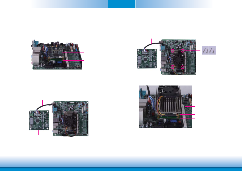
5. Grasp the COM Express Mini module by its edges to press it down on the top of the
COMe-LINK2 debug card.
6. Then, grasp the heat sink by its edges and position it down firmly on the top of the
COM Express Mini module.
COMe-LINK2
COM Express Mini Module
COMe-DEBUG
Cable
Side View of the Module, Debug Card and Carrier Board
7. Use the long mounting screws to secure the heat sink on the top of the COM Express Mini
module and the COMe-LINK2 debug card and connect the cooling fan’s cable to the fan
connector on the COM Express Mini module. The photo below shows the locations of long
mounting screws.
Long screws
COMe-DEBUG
Cable
COMe-LINK2
Carrier Board
COM Express Mini Module
See also other documents in the category DFI Hardware:
- ES300 (2 pages)
- U340 Series (2 pages)
- VS Series (2 pages)
- CD9A3 series (60 pages)
- CD905-B series (68 pages)
- BT700 (71 pages)
- BT700 (71 pages)
- CD905-B2600 (63 pages)
- CD905-B2800 (63 pages)
- CP908-B (104 pages)
- CR908-B (68 pages)
- HR908-B (66 pages)
- HU968 (86 pages)
- ML905-B11C/B16C (76 pages)
- KB968 (68 pages)
- LR905-B18S (93 pages)
- OT905-B series (61 pages)
- CM960-B (1 page)
- CM901-B (72 pages)
- CP900-B (130 pages)
- NP905-B16C (125 pages)
- CR900-B (73 pages)
- CR902-BL (75 pages)
- CR901-B (69 pages)
- CR960-QM77 (81 pages)
- HM920-QM87 (98 pages)
- G5C900-B106 (118 pages)
- HM960-QM87 (101 pages)
- HM961-QM87 (95 pages)
- HR900-B (102 pages)
- HR902-BL (75 pages)
- FS700 (17 pages)
- QB702-B (47 pages)
- QB700-B (73 pages)
- COM100-B (32 pages)
- QB701-B (73 pages)
- NP900-B16C (121 pages)
- COM101-BAT (32 pages)
- COM630-B (50 pages)
- COM330-B (57 pages)
- Q7-100 (31 pages)
- Q7-951 (46 pages)
- Q7A-551 (23 pages)
- Q7X-151 (30 pages)