Chapter 3 – DFI BT9A3 User Manual
Page 22
www.dfi .com
Chapter 3 Hardware Installation
22
Chapter 3
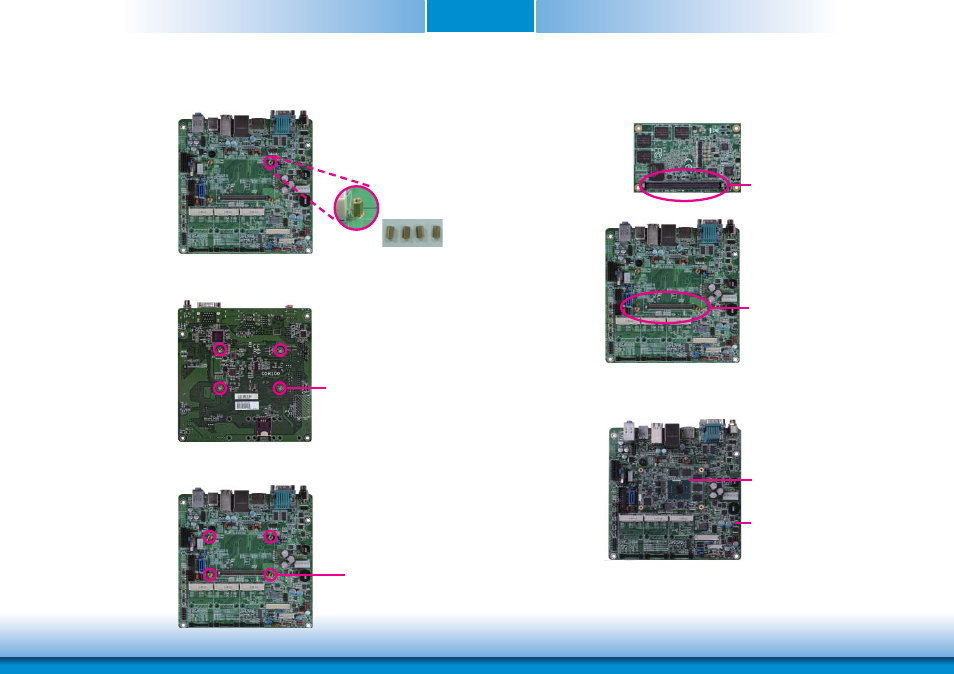
3. While supporting the mounting screw at the bottom, from the top side of the board, fasten
a bolt into the screw.
4. The photo below shows the solder side of the board with the screws already fixed in place.
Bolts
Mounting screw
5. The photo below shows the component side of the board with the bolts already fixed in
place.
Bolts
6. Grasping BT9A3 by its edges, position it on the top of the carrier board with its mounting
holes aligned with the bolts on the carrier board. This will also align the COM Express
connectors of the two boards to each other.
COM Express connector
on BT9A3
COM Express connector
on the carrier board
7. Press BT9A3 down firmly until it is completely seated on the COM Express connector of
the carrier board.
Carrier board
BT9A3
- ES300 (2 pages)
- U340 Series (2 pages)
- VS Series (2 pages)
- CD9A3 series (60 pages)
- CD905-B series (68 pages)
- BT700 (71 pages)
- BT700 (71 pages)
- CD905-B2600 (63 pages)
- CD905-B2800 (63 pages)
- CP908-B (104 pages)
- CR908-B (68 pages)
- HR908-B (66 pages)
- HU968 (86 pages)
- ML905-B11C/B16C (76 pages)
- KB968 (68 pages)
- LR905-B18S (93 pages)
- OT905-B series (61 pages)
- CM960-B (1 page)
- CM901-B (72 pages)
- CP900-B (130 pages)
- NP905-B16C (125 pages)
- CR900-B (73 pages)
- CR902-BL (75 pages)
- CR901-B (69 pages)
- CR960-QM77 (81 pages)
- HM920-QM87 (98 pages)
- G5C900-B106 (118 pages)
- HM960-QM87 (101 pages)
- HM961-QM87 (95 pages)
- HR900-B (102 pages)
- HR902-BL (75 pages)
- FS700 (17 pages)
- QB702-B (47 pages)
- QB700-B (73 pages)
- COM100-B (32 pages)
- QB701-B (73 pages)
- NP900-B16C (121 pages)
- COM101-BAT (32 pages)
- COM630-B (50 pages)
- COM330-B (57 pages)
- Q7-100 (31 pages)
- Q7-951 (46 pages)
- Q7A-551 (23 pages)
- Q7X-151 (30 pages)