Dexaplan BA 611 User Manual
Page 12
11
GB/IE
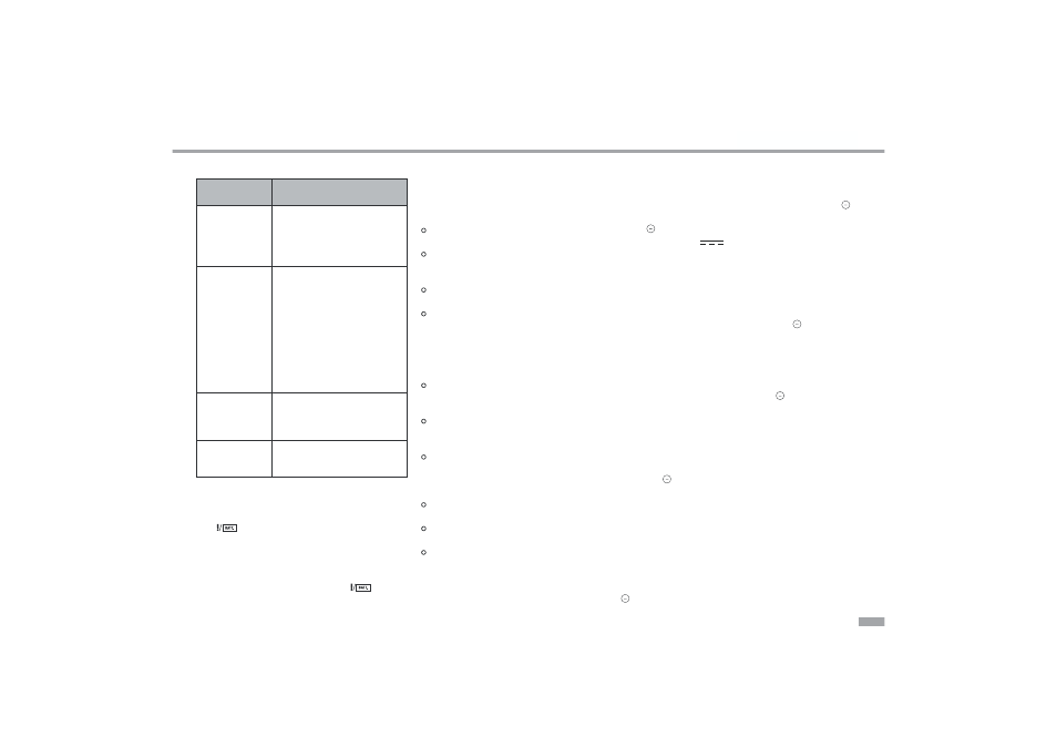
Summary of the sounds
Sound
Meaning
Three pips
The exit delay is activated, the
arming of the alarm and emer-
gency telephone dialler will be
activated after approx 55 seconds.
Siren alarm
The siren sounds
1. Triggered by motion detection
– after the set entry delay in
the cycle:
30 sec. on – 30 sec.
pause – 30 sec. on.
2. Triggered by pressing the
“PANIC” key
u
or
:
as a
panic alarm.
Single gong
sound
Gong switch was set to setting
“I”, the gong function is still not
activated.
Two gong sounds
Motion was detected,
the gong function is activated.
Changing batteries
Alarm unit
If the
LED
q
illuminates once every three seconds
(from approx 7.7V + - 0.5V), then you should renew the
9V block battery. Replace the battery as described in
section “Power supply” under “Alarm unit - 9V block
battery”. In the armed state the alarm unit is supplied
with power for approx. 24 hours after the
LED
q
starts to illuminate.
Remote control handset
If the check LED
a
is weak when the keys on the remote
control are operated and/or the range of the remote control
is reduced then the battery needs to be replaced (battery
12V, alkaline (type CN 23 A or L1028)).
Push the battery compartment cover
f
downwards
using light pressure (see Fig. M).
Replace the battery with a new one. Insert the new
battery, observing the correct polarity (see marking
in the battery compartment).
Push the battery compartment cover back on to the
housing again.
Check that the remote control is working properly.
Optional connections
In order to be able to connect optional external devices
-
tions in the alarm unit:
Remove the screw
S
from the connection compart-
ment cover with a crossheaded screw driver (see
Fig. E).
Push the screwdriver into the recess slot
G
and
cover.
Then you can make the desired connections at the
connection terminals
F
(see “Description of the
connections”). Use cable with a wire cross section
of 0.2 – 0.3 mm, e.g. telephone cable.
Guide all the connected cables out of the alarm unit
through the recess slot
G
.
Put the connection compartment cover
A
back in
place.
Tighten the screw
S
on the connection compart-
ment cover again.
Description of the connections (see Fig. N)
INPUT: If an external connection between INPUT and
is broken a gong sound sounds (if the gong
function is switched on) or an alarm is trig-
gered (in the armed state), however only after
the end of the exit delay; if at the end of the
exit delay this terminal is not connected to
no alarm will be triggered.
:
0V (neutral)
SIREN *: 12V
(max. 150 mA) when the alarm is
triggered (irrespective of whether the internal
siren is switched on or off).
NA:
No function.
Siren *:
You can connect an external siren (not included) operat-
ing at 9 or 12V DC, max. 150 mA to the and SIREN
terminals.
Reed contact:
You can connect a reed contact (magnetic contact as
opening detector (NC), not included) as a door or window
opening detector to the INPUT and terminals. Up to 6
reed contacts can be connected in series.
Other contacts:
The potential-free contacts of other detectors or systems
can be connected to trigger the alarm / dialling function.
Opener contacts (NC) can be connected to the INPUT
and
terminals (with more than one contact: connected
in series).
*
If the power supply from the mains adapter fails then
there is no voltage at the SIREN terminal. The INPUT
terminal remains active during operation from the
backup battery.