2 power wiring, 3 connection between sections – Daktronics CH-2024V User Manual
Page 9
Installation
2-3
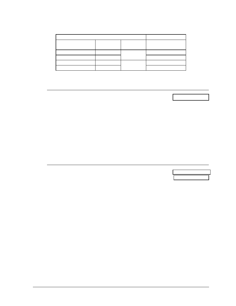
to Drawing A-46539. Connect the signal wires to TB31 as indicated in the table
below.
Control
End
Display
End
J-box Terminal
No.
Wire Color Output No.
TB31 Terminal No.
14 Red/Wht
1*
1
(+)
15 Grn/Wht
2
(-)
16 Blue/Wht
2*
4
(+)
17 Blk/Red
5
(-)
*Auxiliary display(s) require(s) a different output number(s). Consult your CHTS-300
console manual.
2.4.2 Power
Wiring
Reference Drawings: Pwr&Sig Entrance Components ...... Drawing A-46545
The CH-2024V display requires a 120/240 VAC circuit, at 50 amps per line when
equipped with 25W lamps, with a maximum current draw of 87 amps. When
equipped with 30W lamps a 120/240 VAC circuit, at 60 amps per line, with a
maximum current draw of 103 amps.
Route power wires into the display and connect to TB41 in the entrance enclosure, as
shown in Drawing A-46545.
Connect the ground wires to E41 and to a ground rod near the display according
to local codes.
2.4.3 Connection Between Sections
Reference Drawing: Component Locations, CH-2024V ...... Drawing A-46539
Connector Plate, CH-2024V............... Drawing A-46563
There are several digit harnesses located near a 3" hole at the bottom of the upper
section and the top of the lower section that must be routed to the connector plate
located at the bottom of the middle section as shown in Drawing A-46539.
1. Open the access doors and route these harnesses through the 3" holes provided at
the top, bottom and middle of the middle section.
2. Remove the cover from the connector enclosure.
3. Connect the plugs on the digit harnesses to the mating jacks in the connector
plate. Refer to Drawing A-46563.
4. Match the numbers on the plugs with the numbers next to the jacks in the
connector plate.
Included with the digit harnesses is a 4-pin plug labeled "A1-17" (refer to Drawing
A-46545) which is the signal to the lamp driver (A1). Also included is a 9-pin plug
labeled "A1 Power" which is the power to the lamp driver "A1".
Connect the 4-Pin plug (A1-17) from the entrance to the 4-Pin jack located next to the
connector panel. Connect the 9-pin plug labeled "A1 Power" to the 9-pin jack labeled
"A1 Power" in the connector panel.