Electrical installation, Control signal cable, Power wiring – Daktronics CH-1024H User Manual
Page 9: Electrical installation -3, Control signal cable -3, Power wiring -3
Installation
2-3
2.4 Electrical
Installation
2.4.1 Control Signal Cable
Reference Drawings: Driver Enclosure, Power & Signal ... Drawing A-37915
Component
Locations ..................... Drawing A-46464
Color Code, 25-Pin J-Box................ Drawing A-47207
For the display, two conductors of 24 AWG are needed. For distances up to 600 ft. or
22 AWG, up to 1000 ft. are required. Daktronics has 24 AWG direct burial cable,
Daktronics part no. W-1105 with 6 conductors, and 22 AWG cable that must be
pulled through the conduit before burial, Daktronics part no. W-1077 with 2
conductors.
At the control location, mount the signal J-box to a convenient location. Route the
cables and connect them to the wires leading from the connector in the cover,
according to the table below and Drawing A-47207.
At the display, open the hinged access door covering the lamp driver enclosure as
shown in Drawing A-46464. Remove the cover from the lamp driver enclosure. See
Drawing A-37915 for an illustration of the components inside the enclosure.
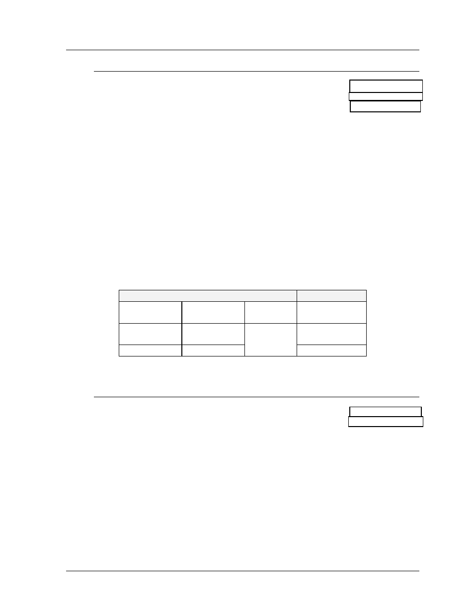
Connect the signal wires to TB31 as indicated in the table below.
Signal Connections
Control End
Display End
J-Box
Terminal no.
Wire Color
Output
No.
TB31
Terminal no.
14
Red/Wht
1*
1
(+)
15
Grn/Wht
2
(-)
*Auxiliary display(s) require(s) a different output number(s). Consult your CHTS-
300 console manual.
2.4.2 Power
Wiring
Reference Drawings: Driver Enclosure, Power & Signal ... Drawing A-37915
Electrical
Installation ....................... Drawing A-46458
A 120/240 VAC circuit (two hot lines, one neutral, plus a ground) must be run into a
load center. See Drawing A-46458. When equipped with 30W lamps, this display is
capable of drawing a maximum of 40 amps on line 1 and 14 amps on line 2 when
lighted.
Route four "hot", two "neutral", and one "ground" wire, 12 AWG from the load center
(Drawing A-46458) to the driver enclosure (Drawing A-37915) in the display.
Connect the ground wire to terminal E41. Connect the two neutral wires to TB41-3
and TB41-4. Connect the hot wires to the load center and the display as in the
example below.