Daktronics, inc – Daktronics Labelle GL100 User Manual
Page 2
ED-8722
Page 1 of 4
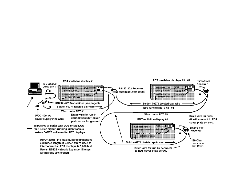
RS232:422 TRANSMITTER / RS422:232 RECEIVER
NETWORK DIAGRAM FOR RDT MULTIPLE-LINE DISPLAYS
All Daktronics direct-wired RDT displays are networked using one RS232:422 Transmitter connected to a PC (via PC-to-Xmtr cable #CDP8000-10-113) or other data
source, and an RS422:232 connected to each RDT display’s DB9 port this is a uni-directional (one-way) network configuration.
IMPORTANT: Use Belden #9271 shielded, twisted-pair wiring (or equivalent for the network run between the transmitter and the first receiver and between
receivers. Note: Connect only one end of the drain (shield) wire from each Belden run to a cover plate screw on a RDT (see diagrams). If there are more that
five RDTs in a network, or for star pattern networks, we recommend the use of our RS422 NET/EXP Network Expander, which supports up to four RDTs while
maintaining power supply and signal strength. Each network Expander can be wired to another Network Expander to create additional “legs” of the display
network (see page 4). A 120 Ohm terminating resistor must be installed at the red and black tabs of the last Receiver in the network and /or at the red and black
tabs on the last Receiver connected to each Expander and at an Expander’s unused signal OUTPUT terminals.
FOR UP TO FIVE ADDRESSABLE RDT DISPLAYS
DAKTRONICS, INC.