Troubleshooting, Initial operation information, Troubleshooting -8 – Daktronics AF-3050-20-R,A User Manual
Page 28: Initial operation information -8
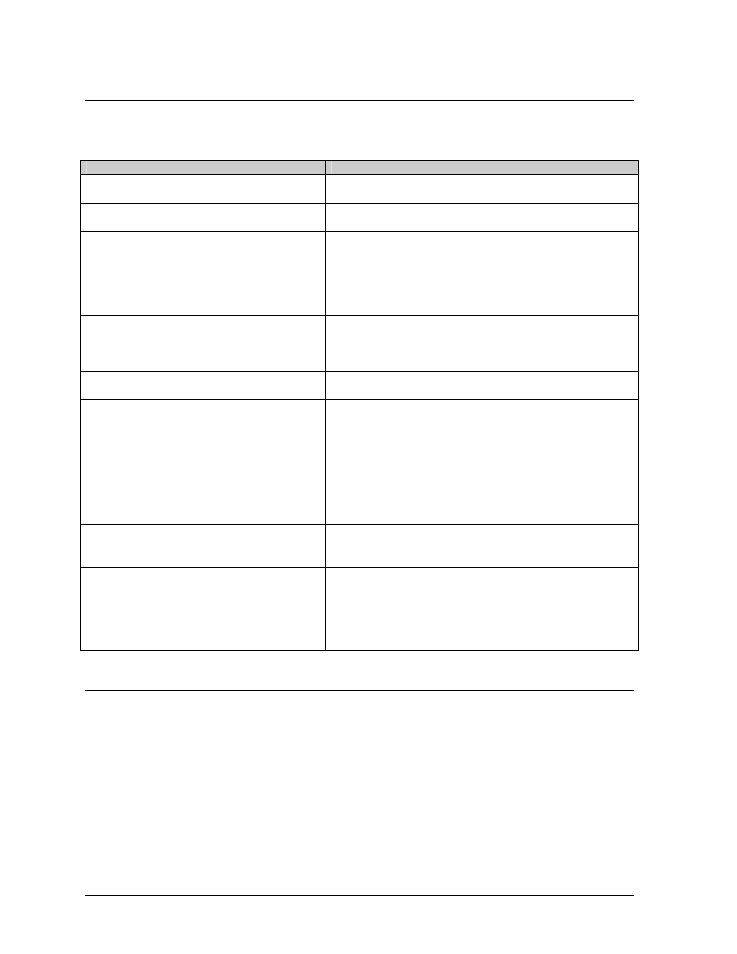
4.9 Troubleshooting
This sub-section contains some symptoms that may be encountered in the signs. This list does not
include every possible symptom, but does represent common situations that may occur.
Symptom/Condition
Possible Cause/Remedy
One or more LEDs on a single module fail
to light.
·
Replace/check ribbon cables on the module.
·
Replace the module.
One or more LEDs on a single module fail
to turn off.
·
Replace/check ribbon cables on module.
·
Replace the module.
A section of the sign is not working. The
section extends all the way to the right side
of the sign.
·
Check/Replace the ribbon cable.
·
Replace the first module/driver on the left side of the
first module that is not working.
·
Replace the second module that is not working.
·
Replace the power supply assembly on the first
module that is not working.
One row of modules does not work or is
garbled.
·
Check/Replace the ribbon cable.
·
Replace first module.
·
Replace controller.
·
Check the fuses in the power termination box.
A group of modules, which share the same
power supply assembly, fail to work.
·
Replace the power supply assembly.
Entire sign fails to work.
·
Check for proper line voltage into the power
termination panel.
·
Check/replace the signal cable to the controller.
·
Check/replace the ribbon cable from the controller
to the modules.
·
Check the voltage settings on the power supplies.
·
Replace the controller.
·
Verify proper use of the software in the operation
manual.
Temperature always reads 32 degrees F/0
degrees C.
·
Check temperature sensor connections.
·
Replace the temperature sensor.
·
Replace the controller.
Sign is stuck on bright or dim.
·
Check Manual/Auto dimming in Venus 1500
software.
·
Check light detector cable.
·
Check light detector for obstructions.
·
Replace the light detector.
·
Replace the controller.
4.10 Initial Operation Information
When first operated, the sign will run through an initialization in which it will display the following:
1. Output
Test
(DDDs)
2. Product Name (Galaxy)
3. Sign Size (Row x Column)
4. Firmware Number (ED10134)
5. Firmware Revision (Rev X.XX)
6. COM1
Configuration
(C1:
V15/RTD)
7. COM2
Configuration (C2: None)
8. Line Frequency (60 Hz)
9. Hardware Address (HW: XX)
10. Software Address (SW: XX)
11. Sign Name
12. Modem if Present (Modem)
Maintenance and Troubleshooting
4-8