Signal, Rs422 cable requirements, Signal connection from computer to sign – Daktronics AF-3050-20-R,A User Manual
Page 19: Signal termination between two (or more) signs, First time operation, Signal -5, Rs422 cable requirements -5, Signal connection from computer to sign -5, Signal termination between two (or more) signs -5, First time operation -5
3.6 Signal
RS422 Cable Requirements
This cable is a 6-conductor shielded cable used to transmit an RS/422 signal. This shielded cable
consists of unpaired wires. They should not be subjected to mechanical flexing after installation.
This cable is not for direct burial and should have one of the following routings:
·
In dedicated metallic conduit
·
Inside buildings
- if cable is not in conduit, keep away from interference signals.
With interference signals (such as power conductors, intercom, etc.) typically a two-foot
separation is required. The maximum length of an RS/422 signal cable is 4,000 feet (1.22
kilometers).
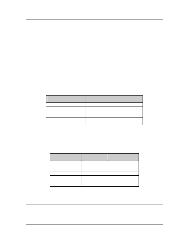
Signal Connect on from Compu er to Sign
i
t
One end of the signal cable should be terminated to the 6-position terminal block in the sign
labeled “RS422 IN” (TB2). The opposite end is terminated at the signal converter (Daktronics part
number 0A-1127-0237) in the control room.
Signal Converter (J4/J5)
Field Cabling
Terminal Block TB2
(RS422 In)
Pin 1 (GND)
Red
Pin 1 (GND)
Pin 2 (RX-P)
Black
Pin 2 (TX-P)
Pin 3 (RX-N)
Brown
Pin 3 (TX-N)
Pin 4 (TX-P)
White
Pin 4 (RX-P)
Pin 5 (TX-N)
Blue
Pin 5 (RX-N)
Pin 6 (GND)
Green
Pin 6 (GND)
Signal Termination Between Two (o More) Signs
r
This is the most common method of terminating signal between two or more signs. A 6-conductor
cable is used and one end terminates at the “RS422 OUT” 6-position terminal block (TB3) on the
first sign. The other end terminates at the “RS422 IN” 6-position terminal block (TB2) in the
second sign.
Sign A
Data Out (TB3)
Field Cabling
Sign B
Data In (TB2)
Pin 1 (GND)
Green
Pin 6 (GND)
Pin 2 (Data TX-N)
Blue
Pin 5 (Data RX-N)
Pin 3 (Data TX-P)
White
Pin 4 (Data RX-P)
Pin 4 (Data RX-N)
Brown
Pin 3 (Data TX-N)
Pin 5 (Data RX-P)
Black
Pin 2 (Data TX-P)
Pin 6 (GND)
Red
Pin 1 (GND)
Pin 6(GND)
Bare (Shield)
N.C.
Note: Refer to Section 4.2 for the modem information. This is found on pages 4-1 and 4-2.
3.7 First Time Operation
When first operated, the sign will run through an initialization in which it will display the following:
1. Output
Test
(DDDs)
2. Product Name (Galaxy)
3. Sign Size (Row x Column)
4. Firmware Number (ED10134)
Electrical Installation
3-5