Setting the security dip switches, Mating the key fob with the display, Setting the display line numbers – Daktronics FLR3-100 User Manual
Page 2
FLR3-100 Installation Quick Guide
Page 2 of 5
DD2291475 Rev 05
6 August 2014
PO Box 5128 201 Daktronics Drive, Brookings, SD 57006-5128
tel: 800-325-8766 fax: 605-697-4700
www.daktronics.com
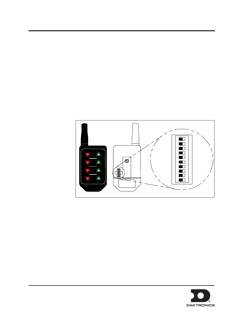
Setting the Security DIP Switches
The FLR3-100 key fob has a series of dip switches on the back to give it a unique address setting. Set these
switches to a unique setting to prevent others from being able to control your display.
1. Remove the small cover on the back of the FLR3-100 key fob radio. Refer to Figure 4.
2. Using a paper clip or a micro screwdriver, set the switches to a unique setting.
Note: Do not change switches nine and zero.
3. Replace the back cover.
Mating the Key Fob with the Display
Follow these steps to mate the display with the FLR3-100 key fob. If these steps are not completed, the
display will not recognize
or respond to the key fob.
1. Turn power on to
the display.
2. While display is
booting up, or
within 5 minutes,
press and hold
Line one Plus
(+) and Minus
(-) keys until the
decimal flashes
3 times. Refer to
3. Once the decimal
point flashes 3 times, release the buttons.
Setting the Display Line Numbers
Follow these steps to map the line number for each display. It is important that each display is set for the
correct line number for it to show the correct price.
1. Make sure the display is turned on.
2. Press and hold the -2 and +2 buttons on the key fob until the host display face begins to dim and
brighten or the decimal begins to flash. This takes about five seconds.
Note: The host display is the display with the radio antenna connected to it.
LL-2855 REV00
CONFIG
ADDR
SYNC
4
3
2
LINE
1
TEST
1 2 3 4 5 6 7 8 9 0
ON
1 2 3 4 5 6 7 8 9 0
ON
Figure 4: FLR3 Key Fob