Daktronics RS-422 Communication User Manual
Page 10
RS-422 Communication Manual
4
6.
1.
2.
o
n
5. Use the keyhole slots on the rear of the signal converter
For displays with an internal surge board only: Route cable through conduit into
the back of the display, being careful not to damage any interior components. Make
the connections to the surge board as normal.
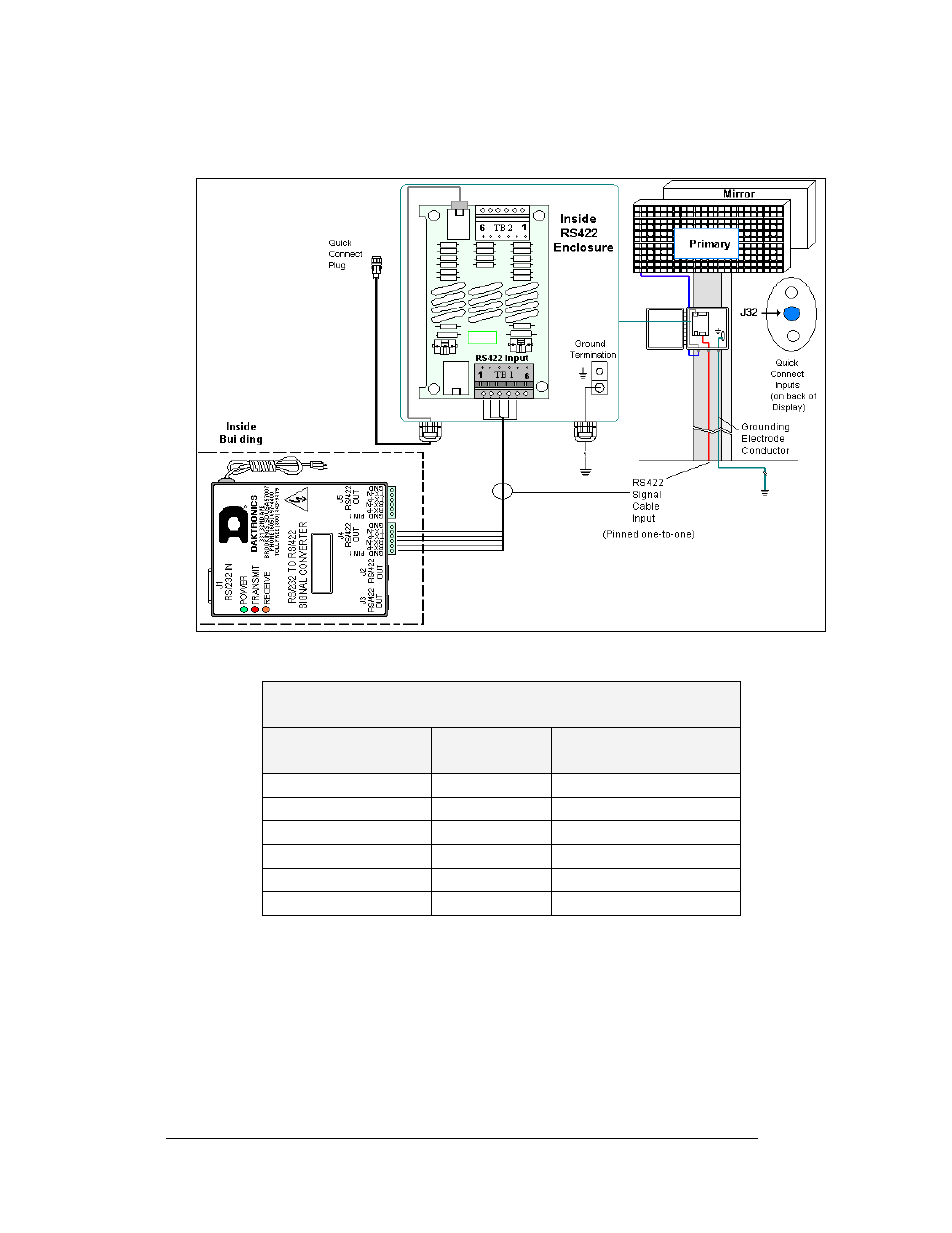
Figure 3: Signal Convert
d Assembly Enclosure
er to Surge Boar
Signal Converter to Surge Board Assembly
Signal Converter
Surge Board Assembly
Field Cabling
(J4/J5)
TB1 (RS422 IN)
Pin 1 (GND)
Shield
Pin 1 (NC)
Pin 2 (RX-P)
Red
Pin 2 (TX-P)
Pin 3 (RX-N)
Black
Pin 3 (TX-N)
Pin 4 (TX-P)
Green
Pin 4 (RX-P)
Pin 5 (TX-N)
White
Pin 5 (RX-N)
Pin 6 (GND)
Pin 6 (NC)
Complete the following steps to mount the signal converter:
ount the signal converter at an interior location.
M
Mount the signal converter within close proximity to
electrical outlet.
a standard 120 VAC grounded
n a wall stud (if possible).
chors that are appropriate for
3. Use #10 round head wood screws to mount the device
4. If a wall stud cannot be used for mounting, use wall a
the wall material.
to mount the device.