Section 5: display maintenance, 1 digit/driver printed circuit board, Section 5 – Daktronics TI-2022 Portable LED Timer User Manual
Page 19: Display maintenance, Digit/driver printed circuit board
Display Maintenance
13
Section 5:
Display Maintenance
IMPORTANT NOTES
:
1. Disconnect power before doing any repair work on the scoreboard.
2. Allow only qualified service personnel access to internal display electronics.
3. Disconnect power when not using the scoreboard.
5.1 Digit/Driver Printed Circuit Board
The TI-2022 uses a single printed circuit board (PCB) that contains all of the electronics
needed to make this system work: digit LEDs, control processors, power input connectors,
horn, and other components. All switches, power systems, and input/output terminations are
connected to the PCB.
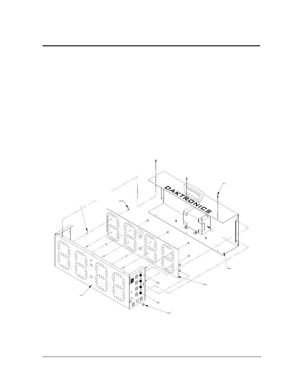
As shown in Figure 9, the PCB is attached to the front panel of the display. Refer to Section
5.2 for instructions on accessing and replacing the PCB.
Battery
(BT-1014)
Nut securing signal jack
Screw
(HC-1489)
Case
Back
Circuit Board
(Part number varies
with model number)
Case
Front
Spacer
(HE-1357)
8-32 Nut
(HC-1354)
Figure 9: TI-2022 Exploded View
Rear Panel
Front Panel
Spacer (HE-1357)
Screw
(HC-1489)
8-32 Nut
(HC-1354)
Nut securing signal jack
Printed Circuit Board
(Indoor: 0P-1153-0002)
(Outdoor: 0P-1153-0004)
Battery
(BT-1014)