Service procedures, Continued – Desa BY35CEH User Manual
Page 11
105522
11
11
SERVICE PROCEDURES
Continued
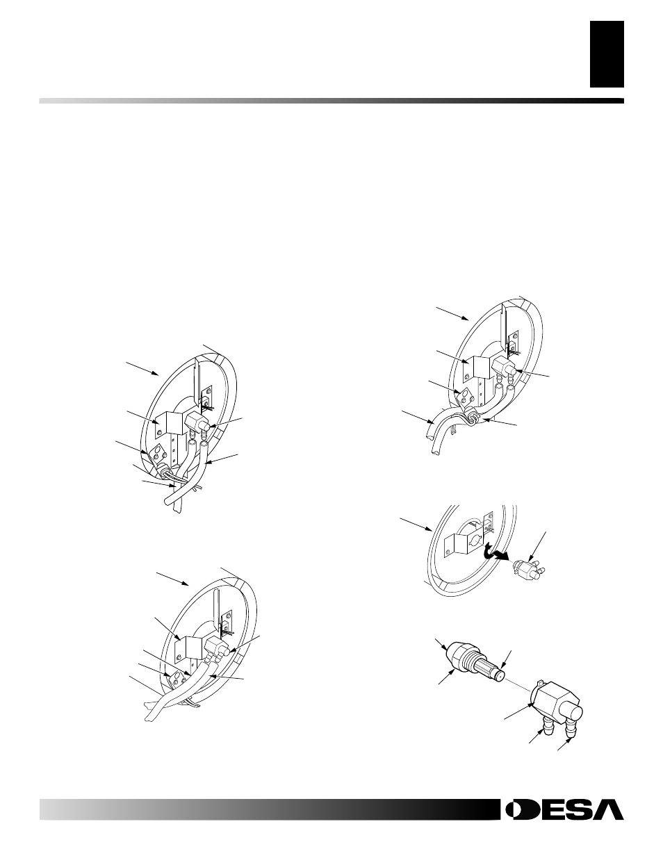
Figure 18 - Removing Air and Fuel Line Hoses (BY100CEH
Model Only)
Figure 20 - Removing Nozzle/Adapter Assembly
NOZZLE ASSEMBLY
1.
Remove upper shell (see page 8).
2.
Remove fan (see page 13).
3.
Remove fuel and air line hoses from nozzle assembly (see Fig-
ure 17, 18 or 19).
4.
Turn nozzle assembly 1/4 turn to left and pull toward motor to
remove (see Figure 20).
5.
Place plastic hex-body into vise and lightly tighten.
6.
Carefully remove nozzle from the nozzle adapter using 5/8"
socket wrench (see Figure 21).
7.
Blow compressed air through face of nozzle. This will free
any dirt in nozzle area.
8.
Inspect nozzle seal for damage.
Figure 19 - Removing Air and Fuel Line Hoses (BY150CEH
Model Only)
Nozzle/Adapter
Assembly
Combustion
Chamber
Fuel Line Hose
Nozzle/
Adapter
Assembly
Combustion
Chamber
Photocell
Bracket
Air Line
Hose
Fuel Line
Hose
Nozzle/
Adapter
Assembly
Combustion
Chamber
Air Line Hose
Photocell Bracket
Figure 17 - Removing Air and Fuel Line Hoses (BY35CEH and
BY70CEH Models Only)
Fuel Line Hose
Nozzle/Adapter
Assembly
Combustion
Chamber
Photocell
Bracket
Air Line
Hose
Nozzle
Adapter
Bracket
Nozzle
Adapter
Bracket
Nozzle Adapter
Bracket
Figure 21 - Nozzle and Nozzle Adapter
Nozzle
Face
Nozzle
Nozzle Seal
Nozzle Adapter
Air Line
Fitting
Fuel Line
Fitting
9.
Replace nozzle into nozzle adapter until nozzle seats. Tighten
1/3 turn more using 5/8" socket wrench 4.5 to 5.1 N-m (40 to
45 in-lbs). See Figure 21.
10. Attach nozzle assembly to burner strap.
11. Attach fuel and airline hoses to nozzle assembly. See Fuel and
Airline Replacement and Proper Routing, page 12.
12. Replace fan (see page 13).
13. Replace fan guard and upper shell (see page 8).
SERVICE PROCEDURES