2 mounting, 3 lnb connector pinouts – Comtech EF Data LNB User Manual
Page 16
LNB Low Noise Block Downconverter
Revision 0
Installation
MN-LNB
2–2
2.2
Mounting
No special tools are required.
Waveguide flange contains 8-32 threaded holes for single unit configuration or #8 screw thru-
holes for optional redundant configurations.
2.3
LNB Connector Pinouts
LNB can be supplied with the following connector configurations, depending on the
model and options:
• 4 pin
• 6 pin
See Table 2-1 below
CAUTION
Use of Power Supply Voltage greater than +24Vdc may cause damage
to the LNB.
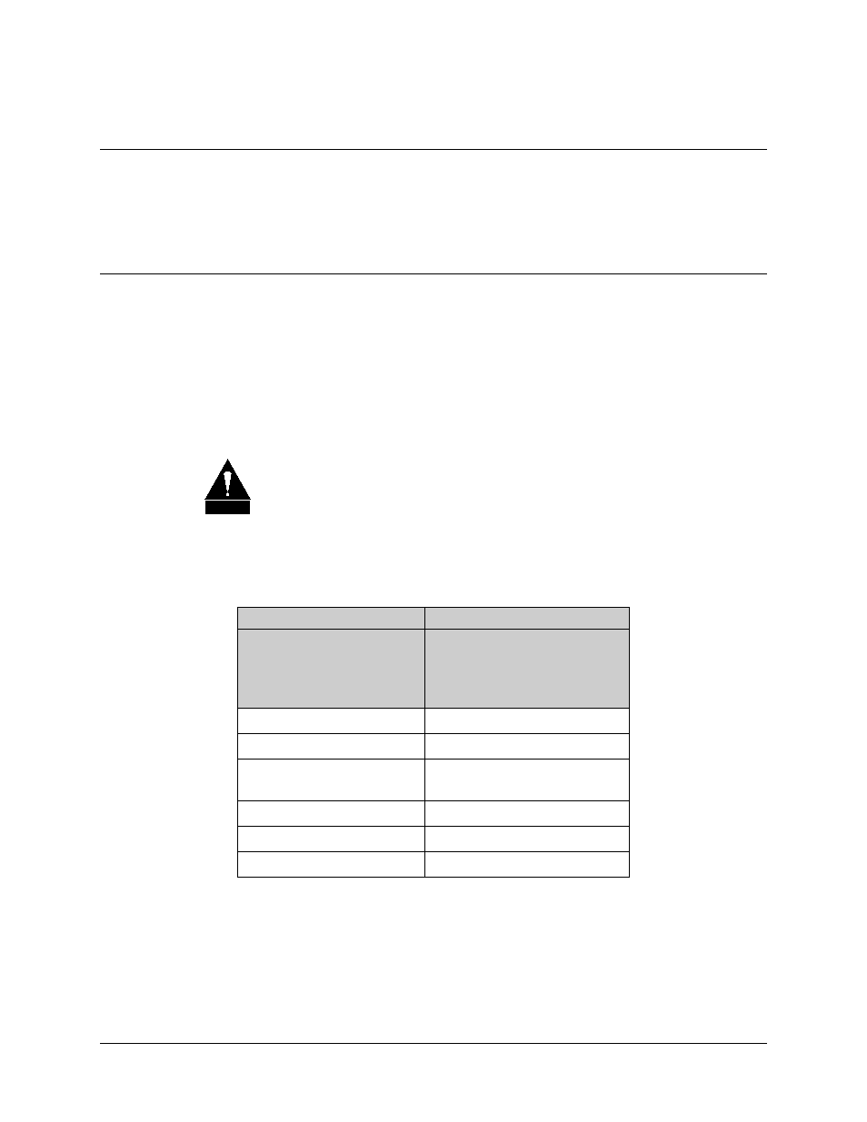
Table 2-1. LNB Connector Pinouts
4-Pin
6-Pin
ITT Cannon KPT02A8-4P
Mating Conn. (Female):
Amphenol: PT06E84S
ITT Cannon MS3112E10-6P
Mating Conn. (Female):
Amphenol MS3116F10-6S
A: +12 to +24VDC Input
A: +12 to +24VDC Input
B: GND
B: GND
C: FLT - NO (NC or open
collector optional)
C: GND
D: Fault common
D: FLT – NO
E: FLT – Common
F: FLT – NC
Normally Open or Closed contact refers to faulted condition
- CDD-880 (124 pages)
- CDM-800 (130 pages)
- ODMR-840 (184 pages)
- CDM-750 (302 pages)
- CDM-840 (244 pages)
- SLM-5650A (420 pages)
- CTOG-250 (236 pages)
- CDM-700 (256 pages)
- CDM-760 (416 pages)
- CDM-710G (246 pages)
- CDM-600/600L (278 pages)
- CDMR-570L (512 pages)
- CDM-625 (684 pages)
- CDM-625A (756 pages)
- CDD-564A (240 pages)
- CDD-564L (254 pages)
- CLO-10 (134 pages)
- MCED-100 (96 pages)
- CDMR-570AL (618 pages)
- CDM-600 LDPC (2 pages)
- BUC Power Supply Ground Cable (2 pages)
- MPP70 Hardware Kit for CDM-570L (4 pages)
- MPP50 Hardware Kit for CDM-570L (4 pages)
- CDM-625 DC-AC Conversion (4 pages)
- CDM-625 DC-AC Conversion with IP Packet Processor (4 pages)
- DMDVR20 LBST Rev 1.1 (117 pages)
- DMD2050E (212 pages)
- DMD-2050 (342 pages)
- DMD1050 (188 pages)
- OM20 (220 pages)
- QAM256 (87 pages)
- DD240XR Rev Е (121 pages)
- MM200 ASI Field (5 pages)
- DM240-DVB (196 pages)
- MM200 (192 pages)
- CRS-150 (78 pages)
- CRS-280L (64 pages)
- CRS-170A (172 pages)
- CRS-180 (136 pages)
- SMS-301 (124 pages)
- CiM-25/8000 (186 pages)
- CiM-25 (26 pages)
- CRS-500 (218 pages)
- CRS-311 (196 pages)
- CIC-20 LVDS to HSSI (26 pages)