Comtech EF Data CRS-200 REDUNDANCY SWITCH User Manual
Page 10
CRS-200
COMTECH COMMUNICATIONS CORPORATION
CRS-200 REDUNDANCY SWITCH - OPERATIONS MANUAL PAGE 8
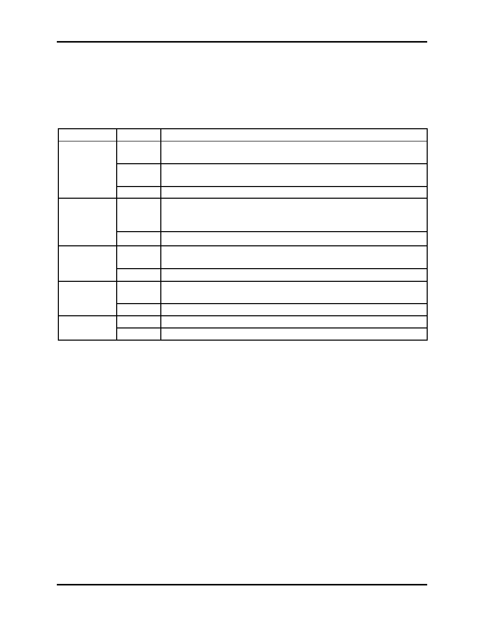
There are 5 LED indicators for each of the 10 TMIs that may be plugged into the rear of the
switch, and 4 of the 5 are repeated an eleventh time for the RMI. These are described in
Table 2 below.
TABLE 2 – MODEM LED INDICATORS
LED
Color
Condition
Unit Status
Red
A Unit Fault exists
Orange
No Unit Faults, but a Traffic Fault exists OR the TMI is not
plugged in
Green
No Unit Faults, or Traffic Faults
Transmit
Traffic
Green
No Tx Traffic Faults
Off
A Tx Traffic fault exists OR the TMI is not plugged in
Receive
Traffic
Green
No Rx Traffic Faults
Off
An Rx Traffic fault exists OR the TMI is not plugged in
On line
Green
The Unit is On Line, and carrying traffic
Off
The Unit is Off Line (standby) - forced by the Switch
Bridged
Orange
Modem is currently being Bridged by Redundant Modem
Off
Modem is not being Bridged
The last indicator is not repeated for the redundant modem, since it cannot bridge itself.
4.2
REAR PANEL - see Figure 2
External cables are attached to connectors on the rear panel of the CRS-200’s plug-in
modules. These comprise the IEC line input connectors, the Data connectors to each
modem, the User Data Interface connector for each traffic modem to the outside world,
the System Alarms connector, the Remote Control connector, and Auxiliary RS-485
connector.
The IEC line input connector for each Power Supply Module contains the ON/OFF switch
for that module. It is also fitted with two fuses - one each for line and neutral connections (or
L1, L2, where appropriate). These are contained within the body of the connector, behind
a small plastic flap.
For 230 volt AC operation, use T0.5A, (slow-blow) 20mm fuses.
For 115 volt AC operation, use T1A fuses, (slow-blow) 20mm fuses.
FOR CONTINUED OPERATOR SAFETY, ALWAYS REPLACE THE FUSES WITH THE
CORRECT TYPE AND RATING.