Auxiliary connectors, Db25 connector to ci-rc-4m-g2, A-pnl-aux96-3 auxiliary connector – Codan Radio MT-4E Analog and P25 Digital - User Guide User Manual
Page 51
MT-4E ANALOG & P25 DIGITAL RADIO SYSTEMS | USER GUIDE
Chapter 6: Radio System Components Page 43
Auxiliary Connectors
The motherboard on the subrack has three auxiliary connectors available, a DB25 connector for direct
connection to a Telex DSP-223 or IP-223, a DB25 connector for direct connection to a CI-RC-4M-G2
Multiple Link Controller and a 96 pin connector typically used to connect to the A-PNL-AUX96-3.
DB25 Connector to DSP-223 or IP-223
Connector J10 is a female DB25 connector which can be used for basic base connections. When
connected to a Telex DSP-223 or IP-223, a standard straight-through male-to-male DB25 extender
cable can be used with some motherboard jumper changes. The IP-223 also requires that 2 pins on
the DB25 (PTT COM - pin2 and MON COM - pin 16) are wired to ground for proper operation.
WARNING: JU108 must be confi gured correctly for DSP-223 or IP-223 or damage can occur.
JU108 A for +13.8 Vdc / DSP-223 or JU108 B for Rx A COR / IP-223
DB25 Connector to CI-RC-4M-G2
Connector J12 is a female DB25 connector which can be used for connecting audio, channel select and
control signal lines to a CI-RC-4M-G2 (second generation) multiple link controller. When connecting to
a CI-RC-4M-G2, a standard straight-through male-to-male DB25 cable can be used.
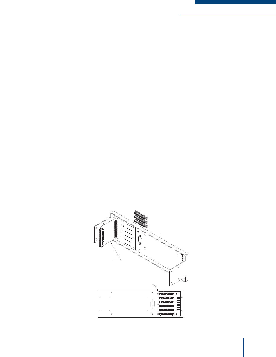
A-PNL-AUX96-3 Auxiliary Connector
An optional component that can be added to the subrack is the A-PNL-AUX96-3 Auxiliary Connector.
The auxiliary connector mounts on the back wrap-around cover of the subrack and connects to the
auxiliary connector on the motherboard. The A-PNL-AUX96-3 brings all of the auxiliary connector
signal lines out to screw terminals for easy connection. These connections are ideal for interfacing
external equipment and allowing easy access for testing and tuning points. The A-PNL-AUX96-3
Auxiliary Connector and the back wrap-around cover are shown in Figure 6-4.
Figure 6-4: Auxiliary Panel Diagram
J1
Tx
A CSel D2
J2
Tx
A CSel D0
Tx A
CSel
D1
Tx
A CSel D3
Rx
A CSel D0
Rx A
CSel
D1
Rx
A CSel D2
Rx
A CSel D3
Tx B CSel D0
Tx B CSel D1
Tx B CSel D2
Tx B CSel D3
Rx B CSel D0
Rx B CSel D1
Rx B CSel D2
Rx B CSel D3
J3
GPIO 1
GPIO 2
GPIO 3
GPIO 4
GPIO 5
GPIO 6
GPIO 7
GPIO 8
GPIO 9
GPIO 10
GPIO 1
1
GPIO 12
GPIO 13
GPIO 14
GPIO 15
GPIO 16
Ground
Ground
Ground
Ground
13.8 Vdc
13.8 Vdc
9.5 Vdc
9.5 Vdc
Rx A
Sql
Over
Rx A
Mode
Rx
A Disc LP
O/P
Rx
A Sql De-emp
Rx B Sql Over
Rx B Mode
Rx B Disc LP
O/P
Rx B Sql De-emp
J4
GPIO 17
Tx
A VSWR Fwd
Tx
A VSWR Rev
Tx
A Dir Mod
Tx A
Sec/Clr
Tx
A PTT
Out
Rx A
Sig
Stren
Rx A
Mute
GPIO 18
Tx B VSWR Fwd
Tx B Dir Mod
Tx B Sec/Clr
Tx B PTT
Out
Rx B Sig Stren
J5
Tx B VSWR Rev
Rx B Mute
Tx A
Bank
Sel
Rx
A Sec/Clr O/P
GPIO 19
Rx A
9.5V
Rx
A 9.5V Mon
Rx
A COR Rly N/C
Rx
A Bank Sel
Tx B Bank Sel
Rx B Sec/Clr O/P
GPIO 20
Rx B 9.5V
Rx B 9.5V Mon
GPIO 21
Rx B Bank Sel
GPIO 22
GPIO 23
J6
Pin 1
Pin 16
Wire Sizes: 22 AWG Min, 16 AWG Max
GPIO 1
GPIO 2
GPIO 3
GPIO 4
GPIO 5
GPIO 6
GPIO 7
GPIO 8
GPIO 9
GPIO 10
GPIO 11
GPIO 12
GPIO 13
GPIO 14
GPIO 15
GPIO 16
GPIO 17
Tx
A Bal I/P
1
Tx A
PTT
Rx
A Bal O/P
1
Rx
A Bal O/P
2
Rx A
COR
Rx
A Disc O/P
Tx B Bal I/P
1
Tx B Bal I/P
2
Tx B PTT
Tx B Subt I/P
1
Rx B Bal O/P
1
Rx B Bal O/P
2
Rx B COR
Rx B Disc O/P
Tx
A Subt I/P
1
Tx
A Bal I/P
2
GPIO 18
GPIO 19
GPIO 23
GPIO 22
GPIO 21
GPIO 20
CONNECTOR
BOARD
SUBRACK REAR VIEW
PLUG IN SCREW
CONNECTORS
A-PNL-AUX96-3
HEADERS AND LABEL
TERMINAL
BLOCK BOARD