5 installing an ae-1 active module – Cloud Electronics AE-1 User Manual
Page 4
AE-1: Installation & User Guide 3
08-07-02 V6
5 Installing an AE-1 Active Module
5a Hardware and Wiring Requirements
The Cloud AE-1 active module is the same physical size as a double UK electrical socket (13A
Type) and can be mounted in the recessed back box provided or be surface mounted in a
standard 35mm deep housing. The AE-1 should be connected to the facility input of the host
mixer or amplifier using 8-Core cable with an overall screen. The AE-1 terminations are
conventional screw terminals while the facility input on the host unit is a 9-Pin sub-D type
connector (sub D-Type connector is supplied with the unit).
It is advised that you are vigilant when wiring the AE-1 as wiring conventions between old and
new host units do vary. Since the AE-1 derives its power from the host unit, certain wiring
errors can cause power supply problems resulting in temporary shutdown of the host mixer or
amplifier; the unit can be reset by switching it off for 30 seconds. If a problem such as this is
experienced, disconnect the facility connector and double check the wiring against the diagram,
also note that we recommend a maximum cable length of 100m (328ft).
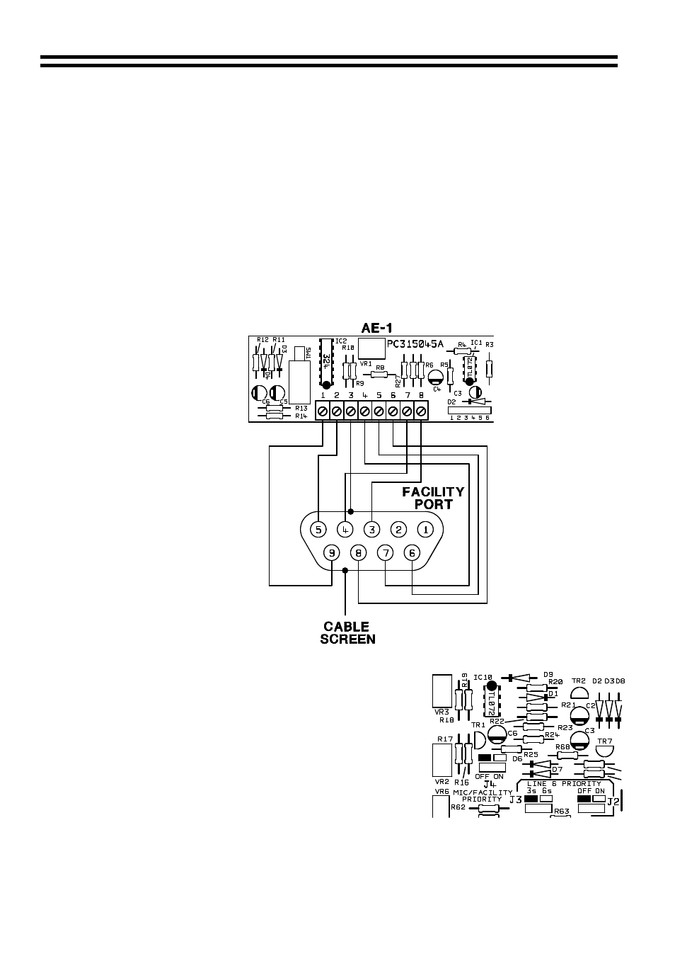
5b Connecting an AE-1
5c Configuring a Z4 or Z8
to an AE-1 Location of Jumper J4
Should you wish the mic signals from the mixer to
override the AE-1 signals, set Jumper ‘J4’ on the zone
board to the ‘ON’ position.
When setting the jumper(s) please ensure that you:
•
Remove the mains cable from the rear of the
product before removing the top panel
•
Only reassemble the unit using bolts/screws
identical to the original parts