2installation instructions, 13 music mute (fire alarm interface), 14 bose equalisation module – Cloud Electronics MPA626 User Manual
Page 11
10
MPA-626: Installation and Operation Manual
13
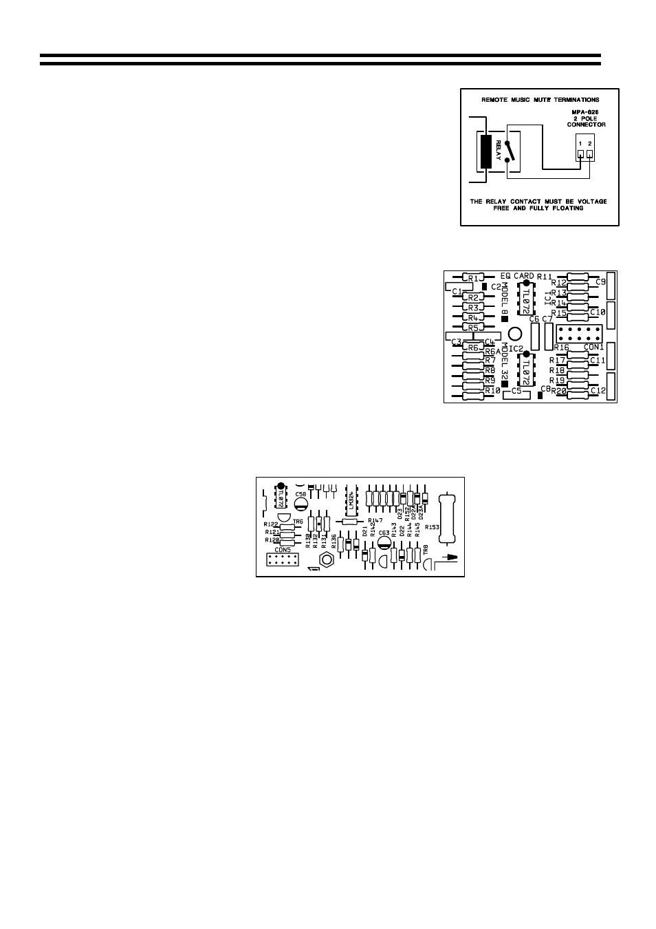
Music Mute (Fire Alarm Interface)
In certain installations, such as licensed premises or retail
outlets within a shopping mall, there may be a local authority or
fire service requirement to mute the music signals via a fire
alarm control panel in an alarm condition. The MPA-626
provides a facility to mute the music signals only, by using a fully
isolated pair of contacts. This is usually a relay mounted close
to the MPA-626, which is powered by the fire alarm control
panel. The relay should close during an alarm condition (the
installation of this relay is normally undertaken by the fire alarm
installation company). See right hand diagram.
14 Bose Equalisation Module
Bose Equalisation Module
The single channel Bose equalisation module is compatible
with the MPA-626; it is available in two different models:
• Model 8 card for use with Bose model 8 speakers.
• Model 32 card for use with Bose model 25, 32 and
102 speakers.
14.1 Installation
Information
The connector for the Bose equalisation module is approximately 50mm from the rear of the
variable line out control. The connector is marked CON5 (see diagram below).
Location of CON5
Important note: Refer to Section 16 before installing the Bose Equalisation module.
14.2 Installation
Instructions
1. Switch off power and remove the mains lead.
2. Switch the output transformer on.
3. Remove the top panel from the unit.
4. Remove the jumper from the main PCB connector ‘CON5’.
5. Next to ‘CON5’ there is an M3 screw through the PCB with a white arrow pointing to it, locate
this screw, remove it, retain it and replace it with the 12mm metal hex spacer.
6. Push the Bose
equalisation module onto the PCB connector; take care to position the
module correctly always using the mounting post to verify correct position of the module.
7. Fit the M3 screw (removed earlier) through the mounting hole into the hex spacer.
8. Replace the top panel.
11-07-02 V4