Wiring, Me-1 series installation guide v2.0 3, Me-1 – Cloud Electronics ME-1B User Manual
Page 3
ME-1 Series Installation Guide v2.0
3
PIN
USE
CAT-5 CORE
1
Left (cold)
White + Orange
2
Left (hot)
Orange
3
Sense
White + Green
4
DC +ve
Blue
5
0v
White + Blue
6
DC -ve
Green
7
Right (hot)
White + Brown
8
Right (cold)
Brown
SCN
Screen
Connector Shell
1
8
1
8
1
8
1
8
ME-1M (Media version)
The Cloud ME-1M is a 100 x 50 mm “Euro-module”, and is designed to clip into a mounting frame with this size cut-out (not
supplied). Suitable mounting frames are available in most European and other territories, to fit local electrical back box dimensions.
Ensure that the back box has a depth of at least 35 mm. The module is secured in place by the six plastic clips (three top, three
bottom).
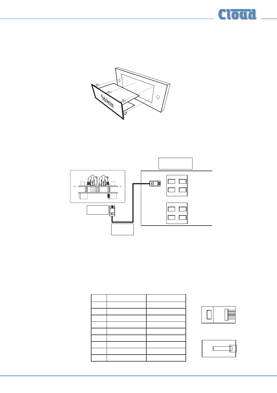
Wiring
The ME-1’s OUTPUT connector should be connected to one of the DCM1’s MICROPHONE INPUTs with screened Cat 5 cable
and shielded RJ45 plugs.
Connect to
Output socket
Screened
Cat 5 cable
MICROPHONE INPUTS
EXTENSION PORTS
DCM-1
1
2
3
4
1
2
3
4
Connect to an
unused Microphone Input
ME-1
OUTPUT
LINK
UK version illustrated
Note that all ME-1s have two RJ45 connectors, OUTPUT and LINK. On ME-1 and ME-1A versions, they are both mounted on the
lower PCB, with the OUTPUT connector on the right (looking at the module rear). On ME-1M versions, they are mounted on
separate PCBs; the OUTPUT connector is on the upper PCB.
IMPORTANT: Because the cables carry low-level audio, only screened Cat 5 should be used, the foil screen of the cable being
bonded to the metal screening can of the plugs. If an ME-1 is being mounted in close proximity to the DCM1, it may be possible to
use ready-made screened Cat 5 “patch” cables of an appropriate length. Otherwise, shielded RJ45 plugs should be crimped onto
the installed screened Cat 5 cable using the pinout shown below.
Mounting frame to suit UK-style
double-gang back box illustrated.