Wiring, Le-1 series installation guide v2.0 3, Le-1 – Cloud Electronics LE-1MB User Manual
Page 3
LE-1 Series Installation Guide v2.0
3
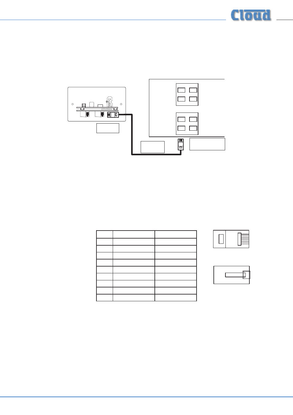
PIN
USE
CAT-5 CORE
1
Left (cold)
White + Orange
2
Left (hot)
Orange
3
Sense
White + Green
4
DC +ve
Blue
5
0v
White + Blue
6
DC -ve
Green
7
Right (hot)
White + Brown
8
Right (cold)
Brown
SCN
Screen
Connector Shell
1
8
1
8
1
8
1
8
Wiring
The LE-1’s OUTPUT connector should be connected to one of the DCM1’s EXTENSION PORTs (Line inputs 1 to 4) with screened
Cat 5 cable and shielded RJ45 plugs. Do not connect any other equipment to the phono sockets of the same-numbered Line Input
on the DCM1.
Connect to
Output socket
Screened
Cat 5 cable
LE-1
OUTPUT
LINK
LE-1
(UK version illustrated)
MICROPHONE INPUTS
EXTENSION PORTS
DCM1
1
2
3
4
1
2
3
4
Connect to an
unused Extension Port
Note that all LE-1s have two RJ45 connectors, OUTPUT and LINK. These are both mounted on the lower PCB, with the OUTPUT
connector on the right (looking at the module rear), and the LINK connector on the left.
IMPORTANT: Because the cables carry low-level audio, only screened Cat 5 should be used, the foil screen of the cable being
bonded to the metal screening can of the plugs. If an LE-1 is being mounted in close proximity to the DCM1, it may be possible to
use ready-made screened Cat 5 “patch” cables of an appropriate length. Otherwise, shielded RJ45 plugs should be crimped onto
the installed screened Cat 5 cable using the pinout shown below.