Wiring, Be-1 series installation guide v2.0 3, Be-1 – Cloud Electronics BE-1B User Manual
Page 3
BE-1 Series Installation Guide v2.0
3
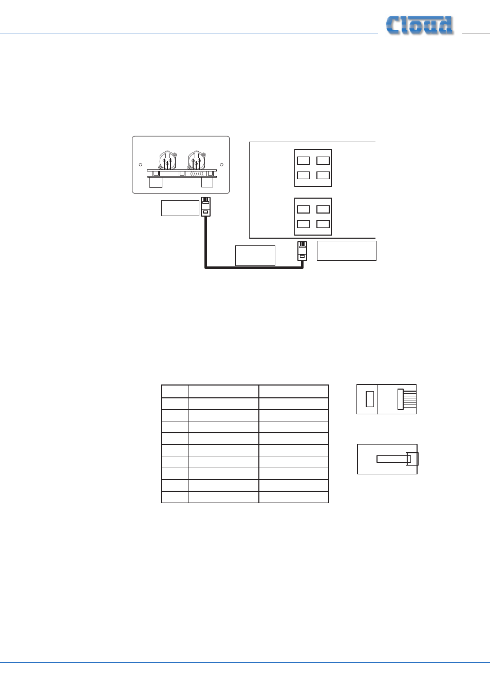
PIN
USE
CAT-5 CORE
1
Left (cold)
White + Orange
2
Left (hot)
Orange
3
Sense
White + Green
4
DC +ve
Blue
5
0v
White + Blue
6
DC -ve
Green
7
Right (hot)
White + Brown
8
Right (cold)
Brown
SCN
Screen
Connector Shell
1
8
1
8
1
8
1
8
Wiring
The BE-1’s OUTPUT connector should be connected to one of the DCM1’s EXTENSION PORTs (Line inputs 1 to 4) with screened
Cat 5 cable and shielded RJ45 plugs. Do not connect any other equipment to the phono sockets of the same-numbered Line Input
on the DCM1.
Connect to
Output socket
Screened
Cat 5 cable
MICROPHONE INPUTS
EXTENSION PORTS
DCM-1
1
2
3
4
1
2
3
4
Connect to an
unused Extension Port
LINK
OUTPUT
BE-1
UK version illustrated
Note that all BE-1s have two RJ45 connectors, OUTPUT and LINK. On BE-1 and BE-1A versions, they are both mounted on the
lower PCB, with the OUTPUT connector on the right (looking at the module rear), and LINK conector on the left. On BE-1M
versions, they are mounted on the upper PCB, again with the OUTPUT connector on the right.
IMPORTANT: Because the cables carry low-level audio, only screened Cat 5 should be used, the foil screen of the cable being
bonded to the metal screening can of the plugs. If a BE-1 is being mounted in close proximity to the DCM1, it may be possible to
use ready-made screened Cat 5 “patch” cables of an appropriate length. Otherwise, shielded RJ45 plugs should be crimped onto
the installed screened Cat 5 cable using the pinout shown below.