Technical data, Installation – Caple C601 User Manual
Page 3
Page 3
C601 user manual.DOC
TECHNICAL DATA
ELECTRIC HOTPLATES
145 mm dia. 1,0 kW - Normal hotplate
1,5 kW - Rapid hotplate
180 mm dia 1,5 kW - Normal hotplate
2,0 kW - Rapid hotplate
Cat: - see nameplate on cover; Class 3
Type "X" hobs
INSTALLATION
For the ELECTRIC WIRING DIAGRAM see figure 2 at the back of this manual. The electrical
power is indicated on the nameplate underneath the hob. A copy of the nameplate is glued
to the cover of this manual.
The appliance must be installed by qualified staff working in accordance with the regulations
in force.
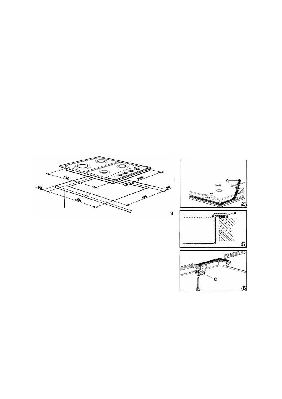
POSITIONING (fig. 3)
Free the hob from the packaging accessories, including the
films covering the chrome plated or stainless steel parts.
Place the hob well away from items of furniture taller than
the hob for built-in installation. Any partition parallel to the
hob must be at least 1 cm lower than the box unit in which it
is installed, and a square opening with sides of 10 cm must
be made under the gas hose elbow
FIXING
A self-adhesive seal (A) is supplied with the hob. This must
be placed under the edge of the box unit, as close as
possible to the edge itself (fig. 4). The seal must run all round the unit to ensure a perfect
seal and prevent moisture from seeping under the hob.
The hooks are secured directly to the box unit using the screws.
Place the hob in the hole in the work top, making sure that the adhesive ensures a good
seal between the edge of the hob and the surface of the supporting unit (fig. 5) and
conclude fixing by tightening the screws which secure the hooks (C) into their seats (fig. 6).