BUG-O Systems Programmable Shape Machine User Manual
Page 10
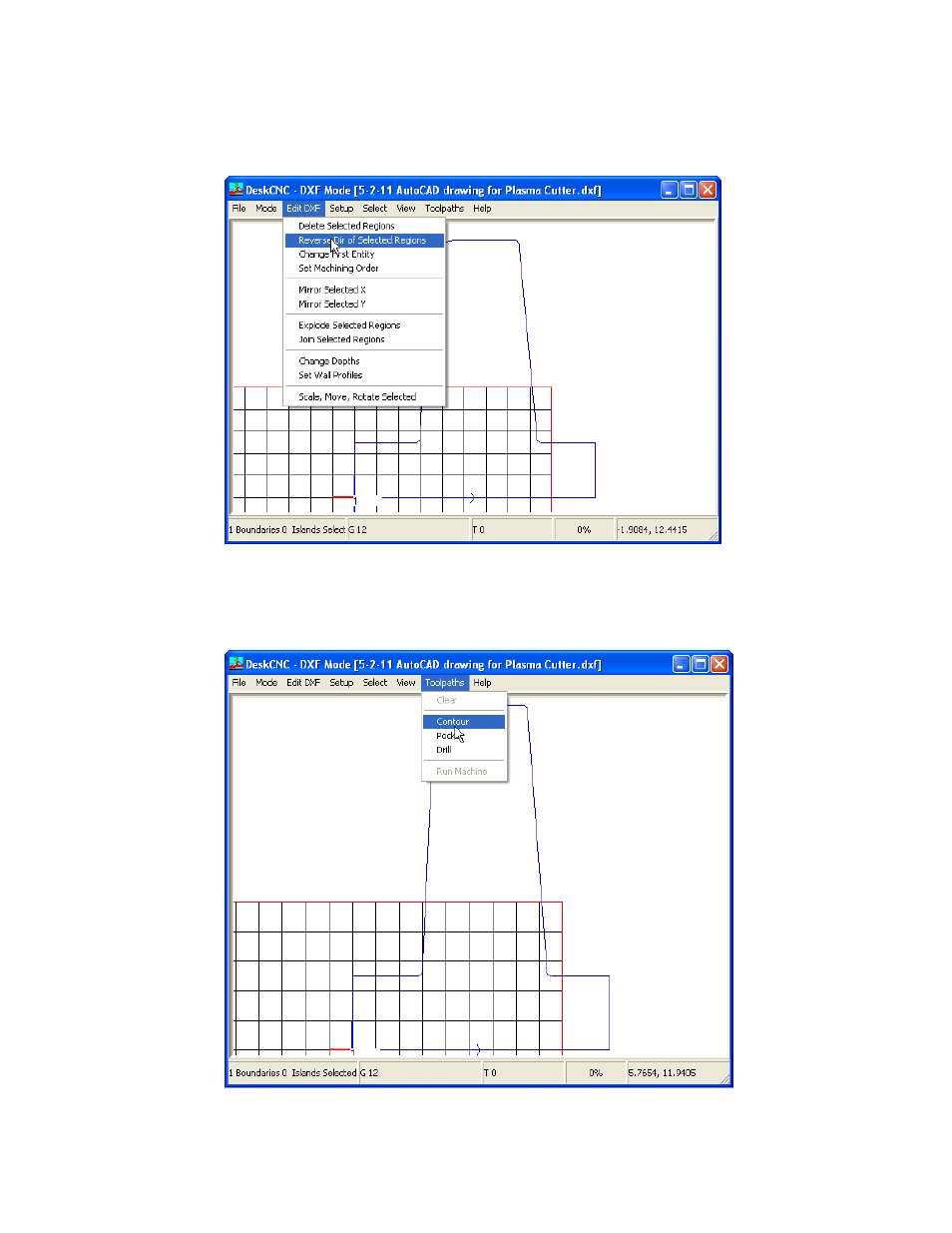
7. To change the direction of the cut, make sure your drawing is still selected by clicking select
and select all. Then click Edit DXF then Reverse Dir of Selected Regions.
8. Once you have the cuts set the way you want, you are ready to make toolpaths for the
machine to read. Click Select menu and select all (If the shape is no longer highlighted), then
click Toolpaths menu and Contour.
See also other documents in the category BUG-O Systems Equipment:
- HOB-O (18 pages)
- Side Beam System (17 pages)
- Flame Cutting (34 pages)
- Trac-Bug (21 pages)
- Programmable Shape Machine (31 pages)
- K-BUG 1200 (21 pages)
- Programmable Gantry System (36 pages)
- CWP-5 (40 pages)
- CWP-7 (41 pages)
- CWP-11 (47 pages)
- CWP-18 (41 pages)
- CB-1P (37 pages)
- CB-3 (30 pages)
- CW-5 (34 pages)
- CWE-5 (40 pages)
- CW-5AX (41 pages)
- CW-7 (43 pages)
- Elbow Cutters 3rd Axis (14 pages)
- CW-11 (46 pages)
- CW-18 (41 pages)
- SE-4PD (48 pages)
- SE-4PTD (40 pages)
- SE-4PD (43 pages)
- FTS-1025 (17 pages)
- BVW-1000 (26 pages)
- AGS-4100 (46 pages)
- Standalone CDS Linear Weavers (20 pages)
- BGW-6000 (47 pages)
- Standalone Pendulum Weavers (18 pages)
- DC IV v.2 (22 pages)
- UNI-BUG II (21 pages)
- PBM-2002 (17 pages)
- BEAM BUG III (23 pages)
- SPB-3000 (26 pages)
- Speed Weaver II (14 pages)
- UNI-BUG III (44 pages)
- CAS-2050 (20 pages)
- BUG-6554 (32 pages)
- CAS-2060 (20 pages)
- BUG-9874 (12 pages)
- STW-2000 (32 pages)
- STW-3000 (26 pages)
- Stiffener Welder (29 pages)
- MDS-1004 (14 pages)