Wire list / wiring diagram, Wiring diagram wire list – BUG-O Systems Speed Weaver II User Manual
Page 11
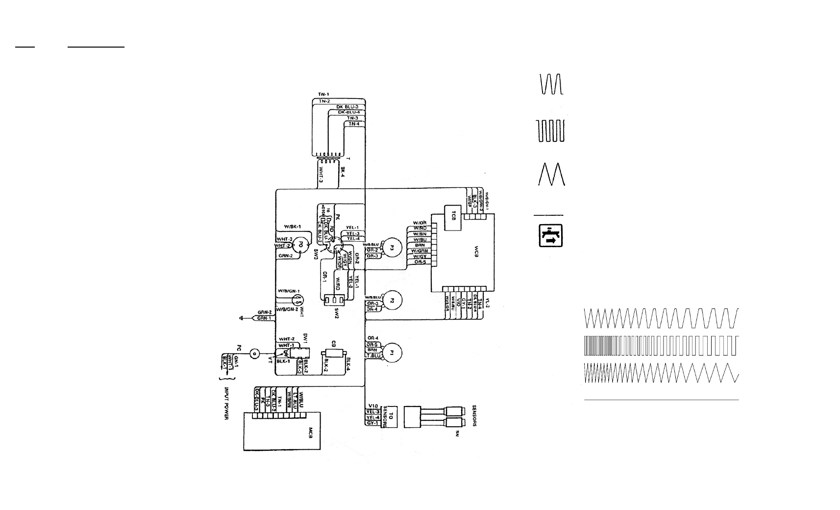
WIRING DIAGRAM
WIRE LIST
ITEM
DESCRIPTION
W/BLK
Switched line power, weave board to tractor outlet
W/BRN
Speed signal voltage, weave to speed board, 0-8 V
W/RD
Weld contact switch control to weave board, 8 or -5 V
W/OR
Made select switch to weave board
W/GRN
Stop on dwell, weave board to selector switch
W/BLU
Fwd/Rev signal, 0 or 8 V, weave board to speed board
W/GY
Step, 0 or 8 V, weave board to selector switch
W/B/OR
Delay left, pot to weave board
W/B/GRN-1
Weld contact, weave board to amphenol
W/B/GRN-2
Weld contact, weave board to amphenol
W/B/BLU
Delay right, pot to weave board
BLK-1
Input line to power switch, hot side
BLK-2
Power line, switch to circuit-breaker
BLK-3
Power line to weave board, for tractor switch
BLK-4
Power line from circuit-breaker to transformer
BRN
Speed signal fr om speed pot to weave board, 0-8 V
RED
Motor current
OR-1
Weld switch to selector switch, 8 V line
OR-2
Selector switch to dwell pot-right
OR-3
Dwell pot-right to dwell pot-left
OR-4
Dwell pot-left to speed pot
OR-5
Speed pot to 8 V supply from weave board
YEL-1
-5 V from speed board to weld switch
YEL-2
Weld contact switch to mode select switch, -5 V
YEL-3
Select switch to sensor connector, -5 V
YEL-4
Select switch to sensor connector, -5 V
GRN-1
Power line ground, line cord to machine case
GRN-2
Ground, case to tractor power socket
LT.BLU
Circuit common (O V), speed board to speed pot
BLU-1
Common (O V), selector switch to motor
BLU-2
Common, speed board to selector switch
BLU-3
Common, transformer C.T. to speed board
BLU-4
Transformer C.T. to weave board, O-V ref.
VIO
Sensor input, left, sensor to weave board
GY-1
Sensor input, right
WHT-1
Power input line
WHT-2
Line power, on-off switch to outlet
WHT-3
Line power, outlet to 20 V.C.T. transformer
TN-1
Transformer sec., supply to speed board
TN-2
Transformer sec., supply to weave board
TN-3
Transformer sec., supply to speed board
TN-4
Transformer sec., supply to weave board
PINK
Motor current, speed board to selector switch
12
9
6. Mode Selector Switch.
The 5-position Switch
(J) is used to select any one of four welding
modes, described below, or to eject the cross rail.
A. RUN: In this mode, power to the tractor is always on, and the
tractor travels continuously both during weave and dwell.
Weave speed and dwell time both affect the weld patterns.
B. STEP: The tractor travels only during dwell, and stops during
the oscillator cross stroke. Changing weave speed does not
affect the weld pattern, dwell time does.
C. TRACTOR STOP ON DWELL: This is a new mode that has
proven very advantageous in certain cases. The tractor and
oscillator travel simultaneously during the weave stroke, both
stop during dwell. Dwell time thus does not affect the weld
pattern, it controls the weld deposit on each side.
D. NO WEAVE: In this mode oscillation is stopped and only the
tractor moves, to make stringer passes.
E. Switching to the fifth position will eject the rail.
A
WELD PATTERNS:
When mounted on a tractor plugged into its panel, the Weaver
produces the above weld patterns; shown for increasing dwell time or
tractor speed from left to right.
D
C
B