BUG-O Systems CWP-5 User Manual
Page 10
10
WIRE FEEDER CONTROLS
The third section of the control panel is the wire feeder controls (Items 12-21 on page 8). An overview of each
wire feeder control is provided below. For more detailed information, refer to the Lincoln Operating manual.
VOLTS Displays actual voltage during welding
CURRENT Displays actual current (amps) during welding
WIRE FEED SPEED Controls the feed speed of the wire. Turn left for slower speeds; right for higher
speeds.
WIRE DIRECTION Controls the direction the wire is being fed through the feeder. UP to return wire to
the spool. DOWN to feed the wire to the gun in order to weld.
FLUX VACUUM Turns the Flux Recovery Vacuum ON and OFF.
PREFLOW Controls flow of shielding gas to the work before the arc is established. The gas
solenoid valve is energized immediately when the gun trigger is closed, but the
time delay before the wire feeder is energized is adjustable from 0 to 1.5 seconds.
Turn the knob LEFT for shorter delays, RIGHT for longer delays.
POSTFLOW Controls flow of shielding gas to the work after the welding has stopped.
Adjustable from 0.5 to 4.5 seconds. Turn the knob LEFT for shorter delays, RIGHT
for longer delays.
PURGE / COLD INCH Control some wire feeder functions without energizing the welding power source.
The momentary UP position energizes the gas solenoid, but not the wire feeder or
welding power source. The momentary DOWN position energizes the wire feeder
but not the gas solenoid or the welding power source.
BURNBACK Provides a precise time delay that allows the wire to be burned off at the end
of the weld. This is useful for those applications where higher speed, fine wire
feeding is used and there is a tendency for the electrode to overrun at the end of
the weld and cause “sticking” in the crater. The delay is adjustable for optimum
burnback depending on wire size, process, procedure, etc.
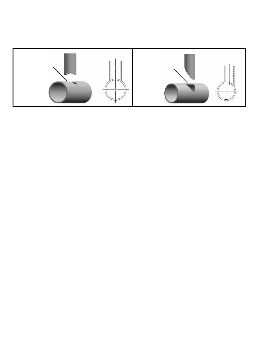
When entering data, use the diameter of the cylinder along whose intersection the cut has been made. Usually
this will be the inside diameter of the nozzle or the outside diameter of the pipe it fits on. This will also allow for
any bevel, if necessary. If no offset, enter “0” or just press “Enter”.
NOTE: If the STOP / RESUME button is pressed, the machine will be in pause mode, and cannot be pro-
grammed. Press the RESET button to get back to the ready mode for programming.
DATA ENTRY
When entering data with the pendant keypad, multiply inches, degrees, or seconds by 100 and enter the
number without a decimal point. For metric dimensions, multiply mm X 10 or cm X 100.
Example: 350 for 3.5 inches,
800 for 80 mm, on metric machines
Press “ENTER” on the keypad after the number is entered.
SAVING PROGRAMS
The machine has 100 storage areas or welds, numbered 0 to 99 in memory. Push the “C” button on the
pendant keypad to change (or set) the program number and enter the desired number. Program data is
retained until reprogrammed. At any time, one of these numbers is selected, it will stay selected even when
power is shut off and turned back on, it will not change until the program number is changed by the operator.
Settings for time delay and number of passes are not saved as part of a program.
ON-CENTER
NOZZLE
OFFSET
NOZZLE