Rear panel – BSS Audio BLU-GPX Owner's Manual User Manual
Page 6
6
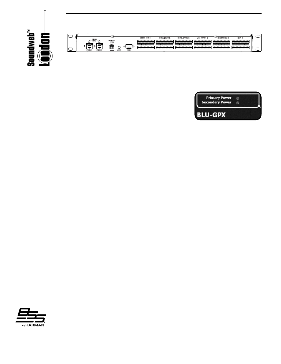
Rear Panel
Primary Power
These two PoE-enabled Ethernet ports are used for system communications and for
providing primary power to the BLU-GPX.
Secondary Power
This 12VDC connector is provided for power source backup. The front panel ‘Power
Supply’ LED provides convenient indication of power
supply status.
NOTE: The BLU-GPX Default Control Panel also provides
visual feedback regarding whether the device is powered
via PoE (‘Primary Power’) or the DC input (‘Secondary
Power’).
NOTE: These models shall be powered by a certified AC/DC power adaptor from FranMar
International Inc., Model FRA030E-S12-4, rated 100-240V~, 50-60 Hz, 0.7A, Class I (for
rated 12Vdc) or powered by certified POE Limited Power Source Adaptor from SL Power,
Model PW180KA4800F01, rated 100-250V~, 50-60Hz, 0.5A, Class I (for rated 48Vdc).
Locate
Pressing the LOCATE switch on the rear of the unit will illuminate the LOCATE switch
on the front and identify the device within London Architect. Similarly the switch will
illuminate if the device is selected from within London Architect or from the LOCATE
switch on the front panel.
RS232
Serial port for connection of external control equipment.
Control Inputs 1-36
These CONTROL INPUTS can be connected to contact closures for controlling binary
parameters, resistor ladders for controlling multi-state parameters, or potentiometers for
controlling continuous parameters, e.g. BLU-3 selector wallplate (Part no. Z-BLU-3). The
BLU-GPX has 47 Common (ground) connections (labelled ‘C’). A multiplicity of Common
connections results in simplified wiring to and from external equipment, reducing the
need to span connections across terminal block connectors. The control ports have two
modes of operation: 2-wire and 3-wire. Provided are 12 Reference connections (Labelled
‘R’) which facilitate 3-wire mode operation.
Logic Outputs 1-23
These 23 Logic Outputs are used to connect ‘tally’ indicator LEDs or relays.
Each Logic Output produces 0V or +5V DC via an internal 440 Ohm resistor and
accompanying internally connected common (ground) connection (C).
An LED connected between one output (Anode, A) and common (Cathode, K) will
illuminate when the LOGIC OUTPUT is activated, without requiring any external current
limiting resistor.
A high sensitivity relay (such as a reed relay) may be driven by connecting four outputs in
parallel. This arrangement will develop 4V across a 500-Ohm coil, providing that all four
outputs are made logic 1 simultaneously.
Opto Output
The last output located on the ‘LOGIC OUTPUTS 13-23’ terminal block is labelled ‘O’.
This is the OPTO OUTPUT, an isolated output which fails safe (open circuit) if the unit
becomes faulty.