Scope of this guide, Starting-up – Bronkhorst Mini CORI-FLOW Quick Start User Manual
Page 2
9.17.052
2
SCOPE OF THIS GUIDE
mini CORI-FLOW™ instruments are highly accurate instruments for measuring and controlling the mass flow rate of liquids and/
or gases, independent of fluid properties. These smart Coriolis instruments offer multiple process values as input- or output
parameters. Many parameters can be read and/or changed using analog or digital interfaces.
Output parameters are: mass flow, density, temperature, totalized mass flow, alarms.
Input parameters are: setpoint (desired mass flow rate for controllers), reset alarm/counter.
This manual will help you start-up your mini CORI-FLOW™ in only 10 steps and contains:
1. Instrument functional properties
2. Check safety properties
3. Check piping
4. Mount/install instrument
5. Leak check
6. Electrical connection
7. Operation
8. Multi-functional switch
9. Purging
10. Zeroing
mini CORI-FLOW™ instruments have modular instruction manuals consisting of:
- Instruction manual mini CORI-FLOW™
(document nr. 9.17.050)
Info about e.g. : sensors, valves, liquid dosing systems, maintenance, tooling, calibration, Kv-value calculation, troubleshooting.
- Operation instructions digital instruments
(document nr. 9.17.023)
- Hookup diagram mini CORI-FLOW™ and CORI-FLOW™ (general)
(document nr. 9.16.044)
- FlowPlot Manual
(document nr. 9.17.030)
Depending on optional fieldbus interface:
Fieldbus/interface description
Manual
Hookup diagram
- RS232 Interface with FLOW-BUS protocol
9.17.027
9.16.044
- FLOW-BUS Interface
9.17.024
9.16.048
- PROFIBUS DP Interface
9.17.025
9.16.049
- DeviceNet™ Interface
9.17.026
9.16.050
- Modbus interface
9.17.035
9.16.066
i
www
These documents can be downloaded from the website:
http://www.bronkhorst-cori-tech.com/en/qrl
or can be sent by e-mail on request.
Notes for temperature considerations
After having used the mini CORI-FLOW™ the first time at low temperature tighten the fluid adaptor screws again in
order to prevent any leakage! Please note: if you do not tighten, the leaking adaptor / fitting can cause damage!
After the first shrinking and tightening of the screws, no further precaution is necessary.
Note that the maximum temperature in the housing of the mini CORI-FLOW™ is 70 °C.
To check this, the internal temperature sensor can be used. Temperature can be readout digitally via FLOW-DDE/
E-8000 (FlowDDE par. 142) or BRIGHT (local readout/control module).
Make sure the temperature value readout here (=actual temperature in housing) will not exceed 70 °C.
STARTING-UP
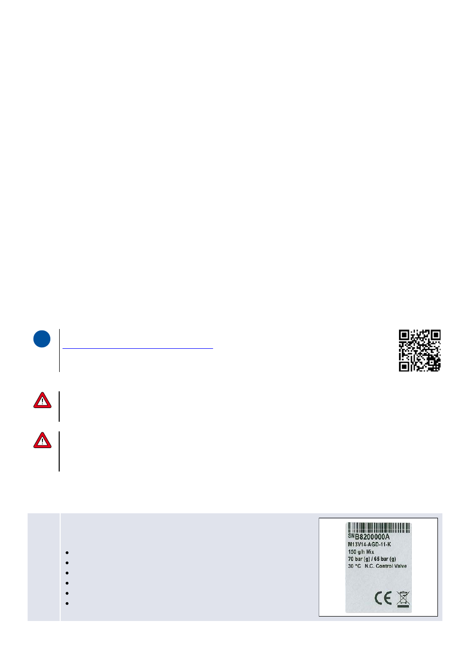
1. Check mini CORI-FLOW™ functional properties
Before installing your Mass Flow Meter/Controller it is important to
read the attached label and check:
Flow rate
Fluid to be measured
Up- and downstream pressures
Input/output signal
Temperature
Valve type (if controller)
© 2015 Bronkhorst Cori-Tech B.V.
3
2. Check test-pressure
The tested pressure is stated on the instrument with a red-coloured sticker.
Before installation, make sure that the test pressure is in accordance with
normal safety factors for your application. If there is no Pressure Testing
Sticker on the device or if the test pressure is incorrect, the instrument
should not be mounted in the process line and be returned to the factory.
3. Check if system piping is clean
For reliable measurement always make sure the fluid stream is clean.
Use filters to assure a particle free liquid stream or a moisture- and
oil-free gas stream. Recommended pore size: 10...40 µm. If back flow can
occur,
a downstream filter and a check valve are recommended too. For high flow
rates select a suitable filter size, to avoid too high pressure drop or cavitation.
4a. Mount/install instrument properly
Install the mini CORI-FLOW™ Meter/Controller in the line and tighten the fittings according to the instructions of
the supplier of the fittings. Mount the mini CORI-FLOW™ instrument, with screws in the body, to a rigid, stiff base
body or heavy mass, such as a wall, heavy rig or stable steel construction. This is essential to achieve optimal
accuracy with the mini CORI-FLOW™ instrument.
4b. Flow direction
Install the mini CORI-FLOW™ in accordance with the direction of
the FLOW arrow. The arrow for flow direction is indicated on the
mini CORI-FLOW™, between process fittings.
4c. Base mounting
Mount the mini CORI-FLOW™ instrument, with screws in the body, to a rigid, stiff base body or heavy mass on a
vibration-free position, such as a wall, heavy rig or stable construction. This is essential to achieve optimal accuracy
with the mini CORI-FLOW™ instrument.
By default the mini CORI-FLOW™ M12, M13 and M14 will be delivered on a special mounting block for achieving
optimal accuracy.This mounting block has a mass and stiffness precisely tuned for the specific model.
Removing the mounting block will cause inaccuracy unless the instrument is firmly mounted on a stiff and rugged
surface.
4d. Mounting position general
For gas and liquid mini CORI-FLOW™ meters can be mounted in any position for a proper measurement.